Pump area (Water Overlay): Difference between revisions
Jump to navigation
Jump to search
No edit summary |
No edit summary |
||
| (One intermediate revision by the same user not shown) | |||
| Line 18: | Line 18: | ||
|notes= | |notes= | ||
* Selecting this option is useful when the [[Pump q (Water Overlay)|PUMP_Q]] value is too large for a single cell. | * Selecting this option is useful when the [[Pump q (Water Overlay)|PUMP_Q]] value is too large for a single cell. | ||
* This requires the pump to consist of 2 discrete polygons. This can either be as a single section with 2 | * This requires the pump to consist of 2 discrete polygons. This can either be as a single section with 2 separate polygons, or as 2 separate sections with 1 polygon each. | ||
|troubles= | |troubles= | ||
* [[Troubleshooting lower threshold for pump is not reached]] | * [[Troubleshooting lower threshold for pump is not reached]] | ||
| | |api=*[[Api session event editor overlay set key value]] | ||
*[[Api session event editor building set attribute]] | |||
*[[Api session event editor functionoverride set attribute]] | |||
}} | }} | ||
{{WaterOverlay hydraulic structure nav}} | {{WaterOverlay hydraulic structure nav}} | ||
Latest revision as of 13:18, 8 October 2026
| Icon | Key | Unit | Range | Description | Default value |
|---|---|---|---|---|---|
 |
PUMP_AREA | boolean | 0 to 1 | When true the Pump is spread across the entire building surface. | 0 |
-
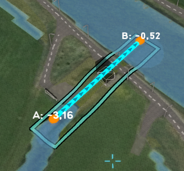 A pump consisting of one line area, with one entry point for the lower and one for the upper Water level areas. It uses a single cell to subtract water, which may be insufficient for high flow rates.
 -
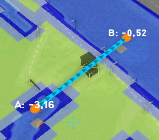 The base type overlay indicating that only one cell is used to subtract water from.
 -
 A pump consisting of two separate areas, one for the lower and one for the upper Water level areas. It uses a lower level threshold and requires multiple grid cells to subtract enough water. It is configured as a PUMP_AREA.
 -
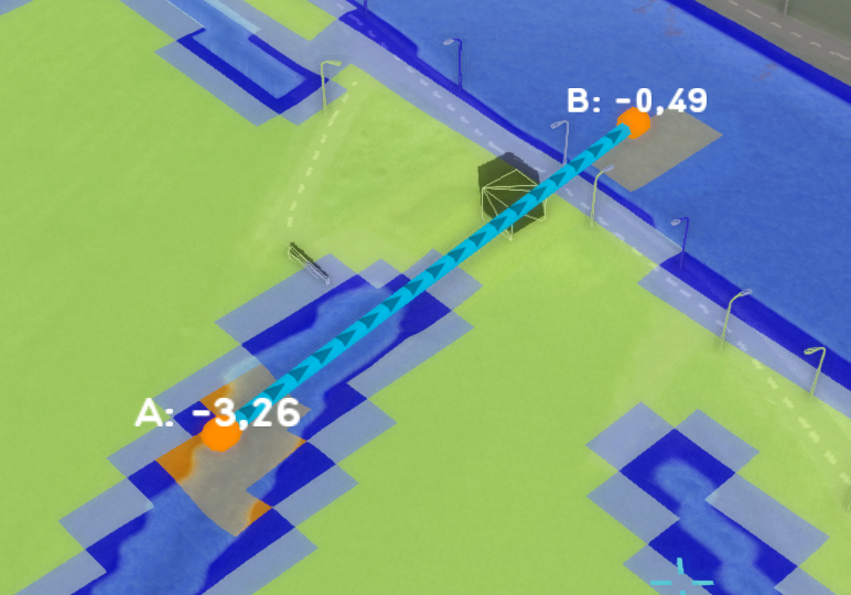 The base type overlay indicating that this pump now uses multiple cells to subtract water from.


Notes
- Selecting this option is useful when the PUMP_Q value is too large for a single cell.
- This requires the pump to consist of 2 discrete polygons. This can either be as a single section with 2 separate polygons, or as 2 separate sections with 1 polygon each.