Brush
The brush is a tool in the editor, which allows you to make a 2D selection in the 3D Visualization of your project for a specific selected Item. Once satisfied with the selection, it has to be applied to add it to, or remove it from, the current 2D geometry of the selected item. While drawing a selection, feedback is given in form of colors, which are explained in the selection legend.
Brush Panel

The brush panel is not directly visible in the editor. It appears when needed, such as when clicking the "Draw Area" button in a Building's detail panel. The brush options that are available for configuration depend on the type of Item, or component of an Item, you are using the brush for.
Brush options
The brush panel offers a number of options, which will allow you to accurately draw a selection in the 3D visualization.
Selection Type

- The type of selection you wish to make. This influences the shapes you draw in the 3D visualization. The appropriate selection type allows for the creation of intricate and precise shapes.
Size

- The size of the selection you are drawing. Depending on the current selection type, the size will influence how large your selection will be. A higher size allows you to draw greater selections more quickly, while a smaller size allows you to make your selection more detailed. For some selection types, such as Ellipse and Poly, the size is used for removing previously selected points.
Operator

- The operation you wish to perform with your selection. Depending on what you are currently drawing a selection for, you may have the option to append to the existing spatial element, or to remove from it. For example, you can add to or remove from a building, but you cannot remove ownership, only overwrite it. By setting the operator to "Add", the selection (when applied) will be added to the spatial element. By setting it to "Remove", the selection (when applied) will be subtracted from the spatial element.
Options

- The options offer ways to make drawing easier. The currently available option is "Hide buildings", which will remove buildings from view. This allows you to draw your selection on the 3D visualization without obstructions.
How to use the brush

The brush panel will appear automatically when you need to draw in the 3D Visualization. Depending on what you wish to draw, the brush will have several options available.
- Select the Selection Type you wish to use.
- If you wish to remove something, set "Remove" to "On".
- In the 3D Visualization, click the left mouse button on a location to start the selection.
- Move your mouse to a new location in the 3D Visualization.
- Click again with the left mouse button to progress or finalize the selection area.
- Press "Apply selection".
Important: Holding your left mouse button allows you to move the Camera. Clicking the left mouse button progresses the selection of an area.
Brush functions explained
The brush panel will appear automatically when you need to draw in the 3D visualization. The Brush will automatically have certain options available or unavailable based on the specific thing you wish to draw. For example, if you wish to draw a road, you will only be able to do so in lines. If you wish to draw terrain, you do not have the option to remove the terrain, etc.
Drawing
There are several ways to draw using the brush. Depending on what you are drawing, the following options may be available. (Note that in the following description, selections are visualized on the client, but not yet applied to the project data. There will be no actual effect on the 3D visualization until the selection is explicitly applied.)
Selection Types
Several selection types exist to allow you to draw in the 3D visualization. The default type depends on what you wish to draw. For example, when drawing a road, by default the brush will be set to "Line" mode.
Block
- Use this mode to draw rectangular areas consisting of square blocks. When moving the cursor in the 3D visualization, a grid will become visible. This grid will align with nearby spatial elements, such as roads, allowing the user to draw a selection parallel or perpendicular to things already present in the project. Click a first time with the left mouse button to start the selection of a rectangle. Move the mouse to expand the rectangle in the desired direction. Click a second time to add the created rectangle to the current selection. Adjusting the size in the brush panel will make the grid larger or smaller.
-
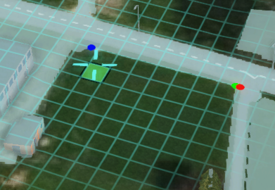 First click
 -
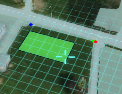 Second click after cursor moved


Line
- The default drawing mode for roads. This mode allows you to draw rectangular areas based on a line between two selected points. Click a first time with the left mouse button in one part of the 3D visualization to start the selection. Move the mouse around in any direction and distance from the first clicked point to create the desired line. Click a second time to confirm the drawn rectangle. Adjusting the size in the brush panel will make the rectangle thicker or thinner.
-
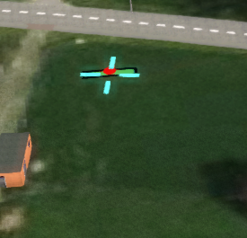 First click
 -
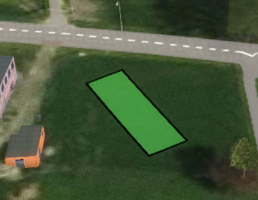 Second click after cursor moved


Poly
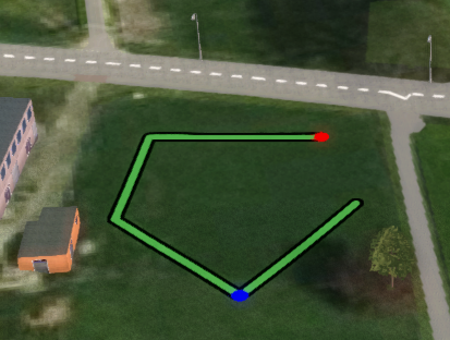
- Use this mode to create polygons. Click with the left mouse button in a part of the 3D visualization to start the selection. Move the cursor and consecutively click with the left mouse button to add more points. To remove a previous point, click on a blue point. Finalize the polygon by clicking on or near the first point indicated with a red color.
-
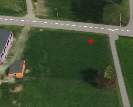 First click
 -
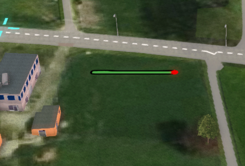 Second click after cursor moved
 -
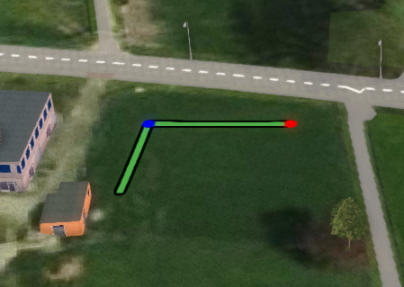 Third click. Notice the blue point
 -
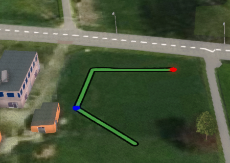 Fourth click
 -
 Fifth click
 -
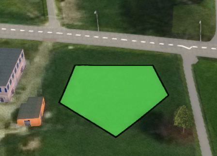 Final click near the red point.


Circle
- Use this mode to create circles. Holding down the left mouse button in one part of the 3D visualization and releasing it in another will create a circle-shaped selection, with the center where the mouse button was pressed. The radius of the circle is the distance between where the mouse button was pressed and where it was released.
-
 First click
 -
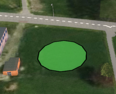 Second click after cursor moved


Ellipse
- Use this mode to create ellipses based on a line segment and two distances to it, along and perpendicular. Click with the left mouse button in one part of the 3D visualization to place the first point. Move the cursor and click a second time to place the second point. This defines the line segment the ellipse will be based on. Move the cursor again away from the line segment to create an ellipse and click a third time to confirm.
- The line segment can also be reset by clicking near the blue point. You can also reset the line's origin (the red point) by clicking near it, provided no blue point exists.
-
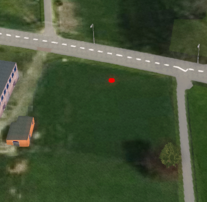 First click as red point
 -
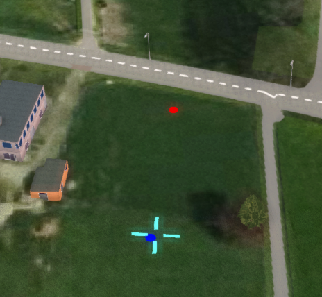 Second click as blue point after cursor moved.
 -
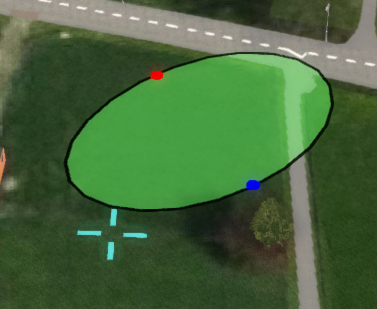 Moving the mouse after the second click.
 -
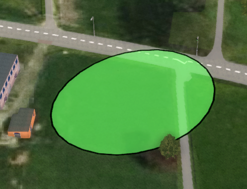 Third click to confirm ellipse


Polygon pick
- Use this selection type to create selections based on existing visible items, such as building and terrain sections. Clicking on a section of a building in the 3D visualization will add the shape of that section to the selection.
-
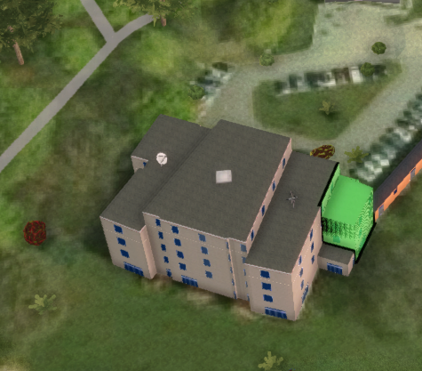 First clicked section
 -
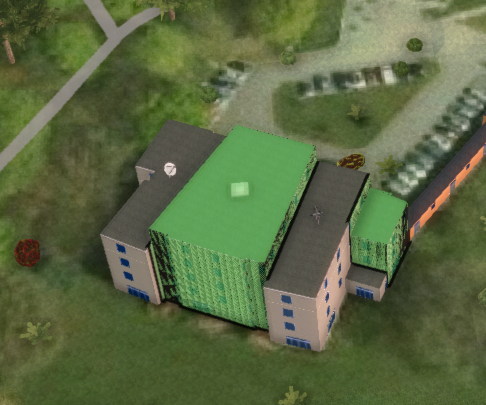 Second clicked section.
 -
 Third clicked section.
 -
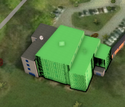
 Clicking second section again removes it.
 -
 Fourth click on road.


Blueprint
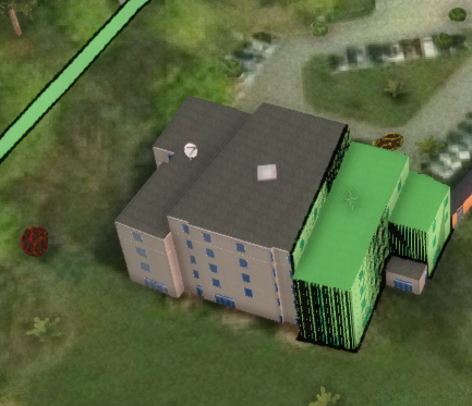
- Use this selection type to create more detailed selections based on existing areas or geo-data files, such as GeoJSON and DXF files. Click From Area to select an area to apply its geometry to the current selection. Click on From Wizard to open the Geo Data Wizard and follow its step to obtain geometries and apply these to the current selection.
-
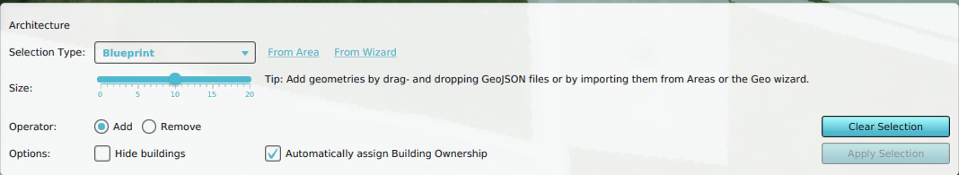 Click From Area hyperlink.
 -
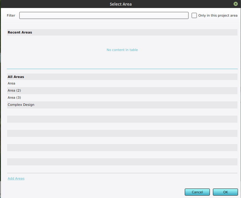 Select Complex Area from selection panel.
 -
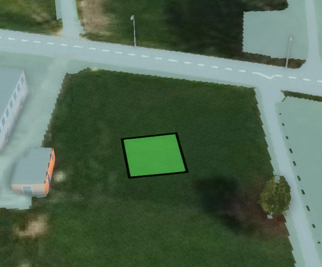
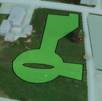 Resulting selection based on area.
 -
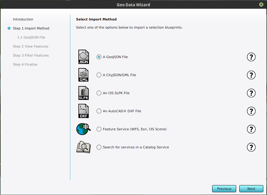 Alternatively click From Wizard to open the Geo Data Wizard.


Single
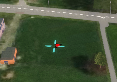
- This mode is automatically used when a point needs to be selected. Clicking anywhere in the 3D visualization will place the point there. Only a single point can be placed.
-
 First Click.

Fine-tuning your selection
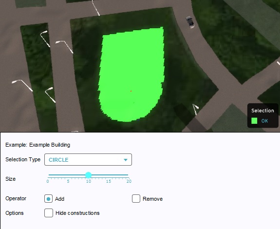
While making a selection, if you wish to make a selection composed of multiples of the same shape (for example, a large rectangle with an adjacent square), you can draw these shapes consecutively. When you begin drawing the second shape, the first shape remains drawn as selection.
You may also wish to combine some of the available drawing modes to create a more complex shape. By switching between drawing modes, without applying or clearing your selection in between, it is possible to preserve a selection made with one drawing mode and add to it with another. For example, to create a square building with a rounded front, you can draw the rectangular area in block mode, switch to circle mode, and draw a circle overlapping the rectangle.
Besides adding to your selection, it is also possible to subtract. Drawing in an unselected area adds to the current selection, while drawing over a selected area subtracts from it. For example, to create a square selection with a concave circular front, you can first draw a square selection, and then draw a circle on the existing selection, making it subtract instead. (Please note that this is different from "Removing".)
-
 Combining selection types
 -
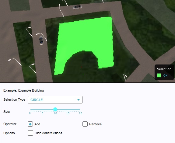 Subtracting a selection


Validity
Making a selection is subject to validity. For more information on validity, please see Drawing validity.
Applying

When you have made a selection, you can use the "Apply Selection" button. At this point, the selection is used to place the Building, Zone, Area, ownership or anything else you might have been drawing, in the 3D Visualization.
Removing
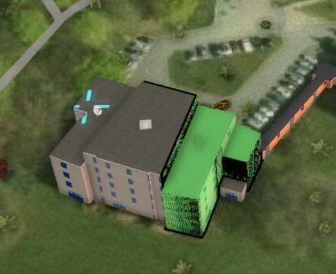
The brush can often also be used to remove elements or properties from the 3D visualization. To do this, you can set the "Operator" setting to "Remove". You will notice your area for valid selections will be (partially) inverted. Places where you were unable to create a valid selection could now be valid, and places where you could make a valid selection will likely be invalid. This is because when you wish to remove something, you must be able to make a valid selection of it. Generally, new elements cannot be placed where an existing element already exists.
-
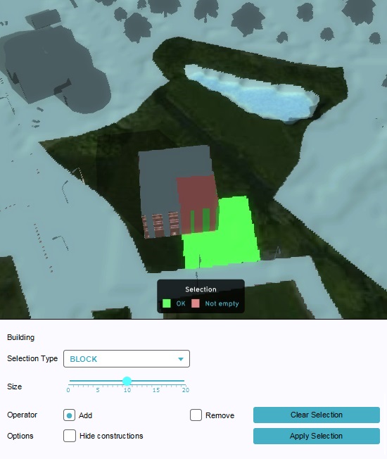 Validity of a selection when adding a building.
 -
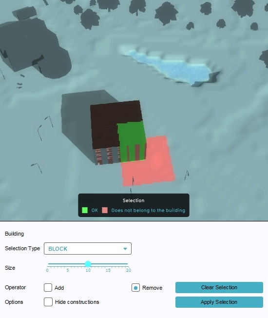 Validity of a selection when removing the building.


Clearing a selection
Use the "Clear Selection" button to cancel the current selection and start over. This undoes the selection you have made and will not be applied, thus having no effect.
How-to's
API Endpoints
- Api session event editor building add polygons
- Api session event editor building remove polygons
- Api session event editor area add polygons
- Api session event editor area remove polygons
- Api session event editor zoning add polygons
- Api session event editor zoning remove polygons
- Api session event editor neighborhood add polygons
- Api session event editor neighborhood remove polygons
- Api session event editor plot add polygons
- Api session event editor terraintype add polygons
- Api session event editor measure add grid polygons
- Api session event editor measure remove grid polygons
- Api session event editor measure add terrain polygons
- Api session event editor measure remove terrain polygons
- Api session event editor measure add geotiff polygons
- Api session event editor measure remove geotiff polygons
- Api session event editor measure add levee polygons
- Api session event editor measure remove levee polygons
- Api session event editor measure add upgrade polygons
- Api session event editor measure remove upgrade polygons
- Api session event editor parametric set polygons