Demo Dxf Import Project

The Demo DXF import project is available for all users and can be found in the main menu under Edit projects. This project does not count towards your license.
This project is intended for Urban planners, architects and consultants.
This project showcases how to import a DXF file into the project, how to add a Geotiff to a measure.
In this demo project an architectural plan [1] is imported to a location in the Netherlands by means of an DXF file. This file is made in AutoCAD, slightly adjusted for demo purposes and exported to DXF.
About the project
This project contains a potential project development area where several architectural plans are situated. The project area partially consists of open land, a few waterways, and a forest and is situated near Tilburg in the Netherlands. The content of each architectural plan is stored in DXF files that were prepared beforehand. Each DXF file is imported as a measure and further enriched with Grids and GeoTIFFs that adjust the Digital Terrain Model when applied.
Explore the current situation
- Click anywhere in the 3D Visualization, and use the arrow keys on your keyboard to move around. You can also pan the camera by clicking and dragging with the left mouse button. Use the scroll wheel to zoom in- and out. By right-clicking and dragging you can rotate the camera.
- Zoom out and observe the current situation. You can see a big empty plot of land to the right of the roundabout. This is the area where we will load a new plan.
-
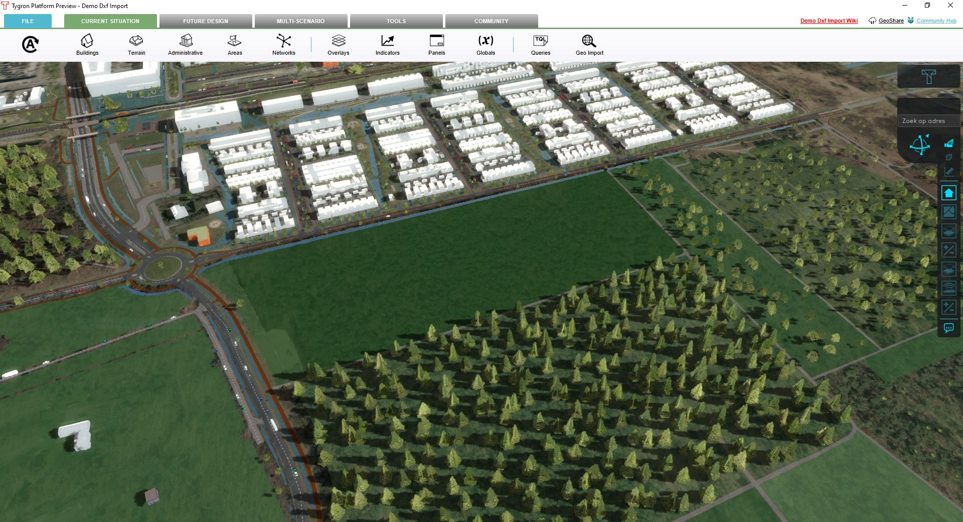 The Area where the new plan will be imported

Import DXF file
- First go to the How to import a DXF tutorial. Use the "dxf_plan_with_water.dxf" from demo_projects/demo_dxf_import/dxf_data on the Public GeoShare. To access the Public GeoShare click on the top right link in the Ribbon bar.
- When prompted in the Geo Data Wizard, choose import as measure and also as a new measure. We will therefore be designing a Future Design project.
- When prompted for function mapping just use One function and pick "placeholder" as a function for now. All other steps can be left as default.
- When the Geo Data Wizard has finished, go to the Future Design tab and click on the Measures button on the Ribbon bar.
- Notice a new Measure has been created on the Left Panel. There are already Example Measures present, these can be used to compare your imported measure if you so wish. It should yield the same results.
- Click on your imported measure and also expand it by clicking on the flag icon next to it. Notice that the Measure contains buildings. These are the buildings which were present in the DXF file and which were identified as building in the Geo Data Wizard.
- With the measure still highlighted go to the Right Editor Panel and click on Activate Measure.
- The Test Run will start and the new plan will appear. Notice that the plan is visualized as one big building. We will fix this in the next section. For now you have created a new measure which was imported from a DXF file.
-
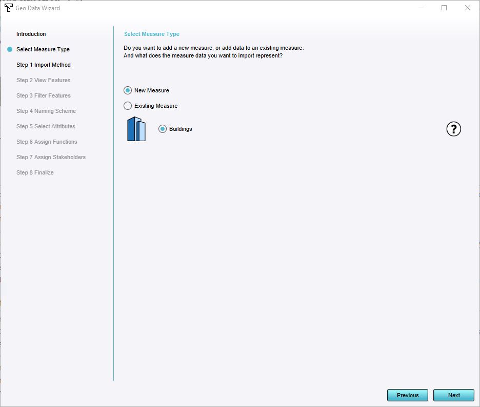 Choose New Measure
 -
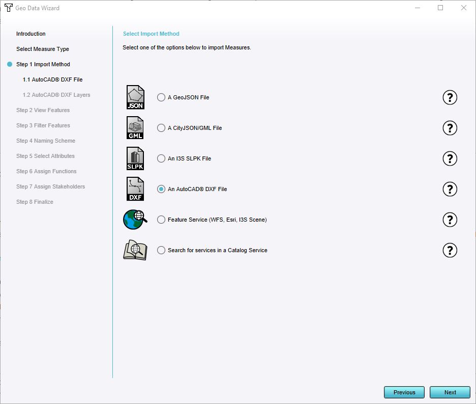 Choose Import AutoCAD DXF file
 -
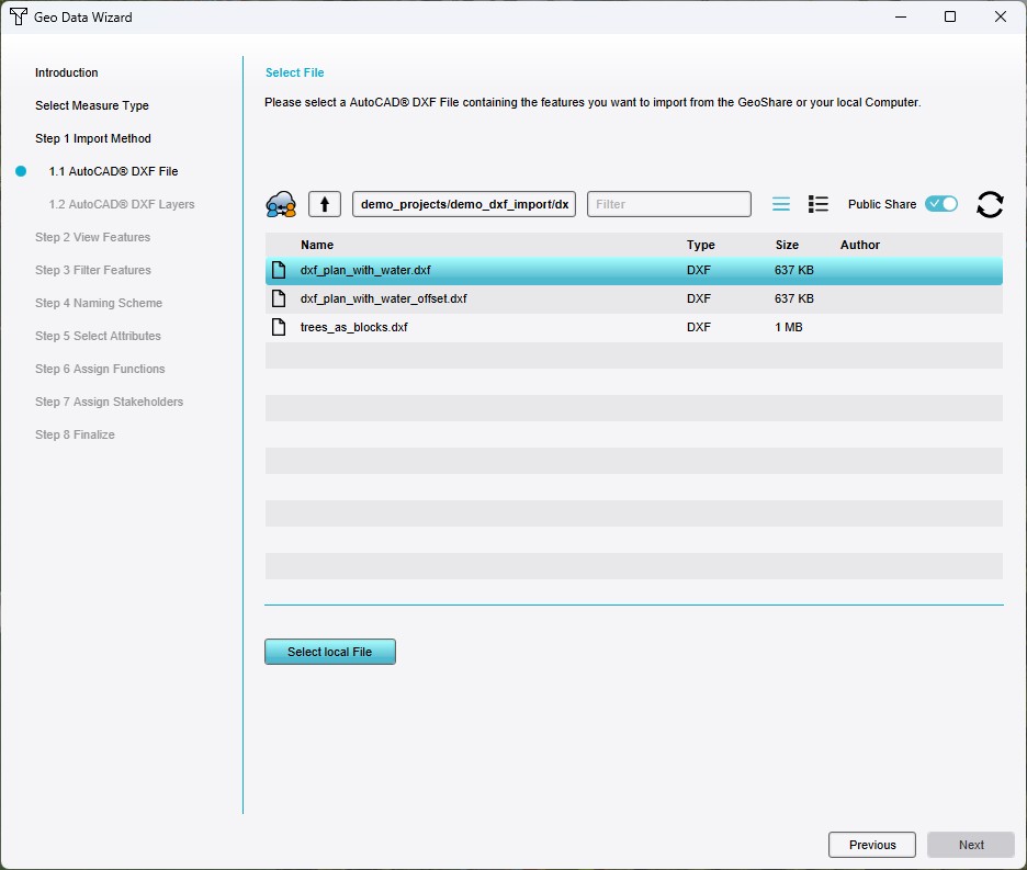 Choose DXF file from Public Share
 -
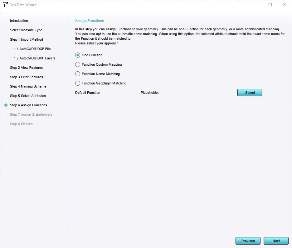 Choose One Function
 -
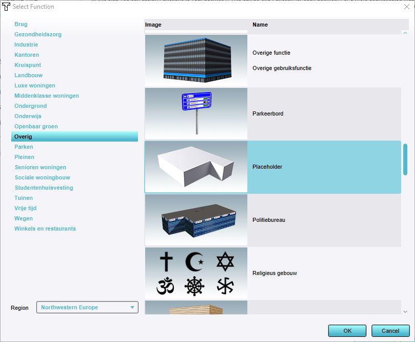 Choose Placeholder function
 -
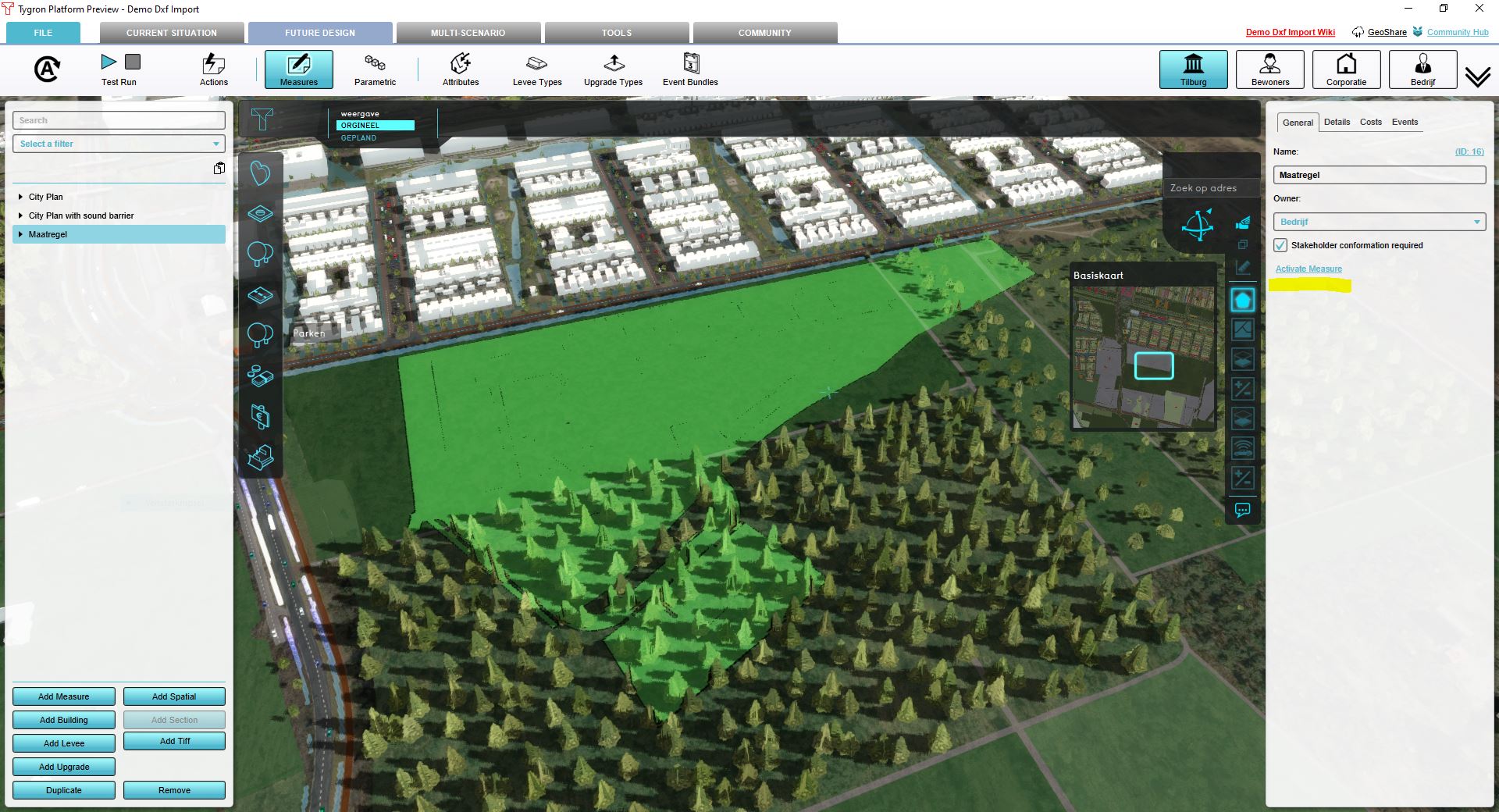 Activate Measure


Use Geo Plugin to map functions
- In this example we will use a Geo Plugin to automatically map features imported from a DXF file to Functions, which will be used to create Buildings that in turn can be combined into a single Measure.
- For this demo this Geo Plugin has already been created and configured. To learn how to make your own Geo Plugin just follow this how-to: How to create a Geo Plugin to import Buildings from a DXF
- First stop the Test Run if it is still Running. This will deactivate any activated Measures and allows you to edit the Current Situation of your project.
- Select the Tools tab on the ribbon bar and click on the Geo Plugin button.
- On the Left Panel a list of existing Geo Plugins is shown.
- Click on the "DXF Matcher" Plugin entry and go to the Right Panel for its properties.
- Go to the Geo Links Tab. A list of Geo Links is shown. Every link corresponds to a Tygron Function with a Layer or Block reference in AutoCAD.
- Click on one of the Geo Links. An attribute window appears at the bottom of the Editor Interface which shows all the correspondences made for each Link. we will not go into them right now. If you want to learn how to make your own just follow this how-to.
- It is sufficient to know for now that the Geo Plugin will match with the AutoCAD layers and the imported DXF will visualize correctly.
- To prevent the measure from appearing as a single building, re-import the DXF using the Geo Plugin settings.
- So as before go to the Future Design Tab and hover over Measures. Choose import Geo Data. This will open the Geo Data Wizard again.
- When prompted to Select Measure Type choose import as new Measure.
- Click Next and keep all settings default until the Wizard prompts you to Assign Functions.
- Choose the Function Geo Plugin Matching option. Choose the Demo Plugin "DXF Matcher" from the Drop-down list. Click Next and then Click Finish
- A new Measure has been created to use The Geo Plugin to apply different Functions to different elements in the DXF file.
- Activate the Measure as before. Notice that the plan is imported correctly now. If you want to compare you can always activate the Example Measure to check for any errors.
-
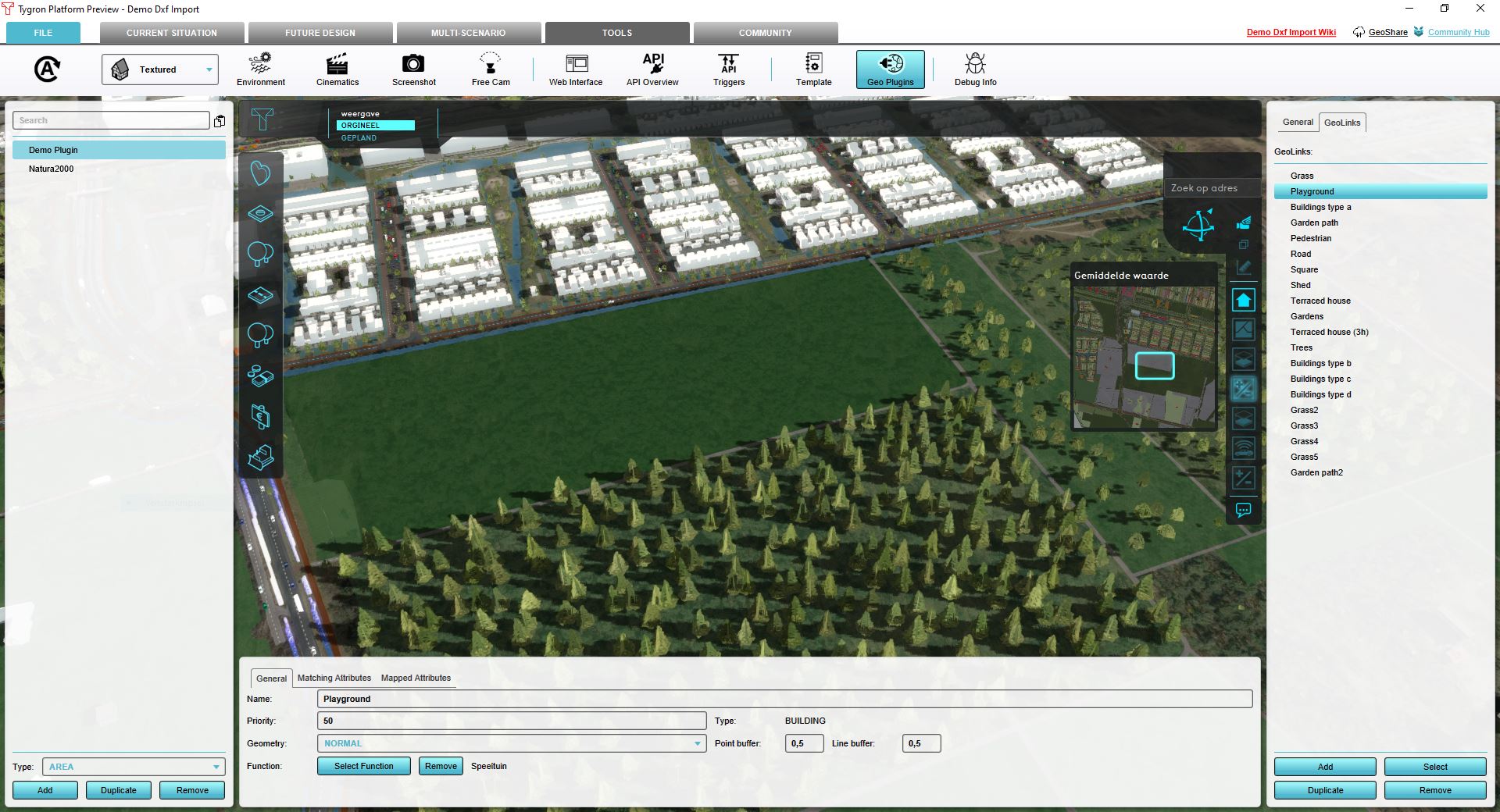 Explore current Building Plugin
 -
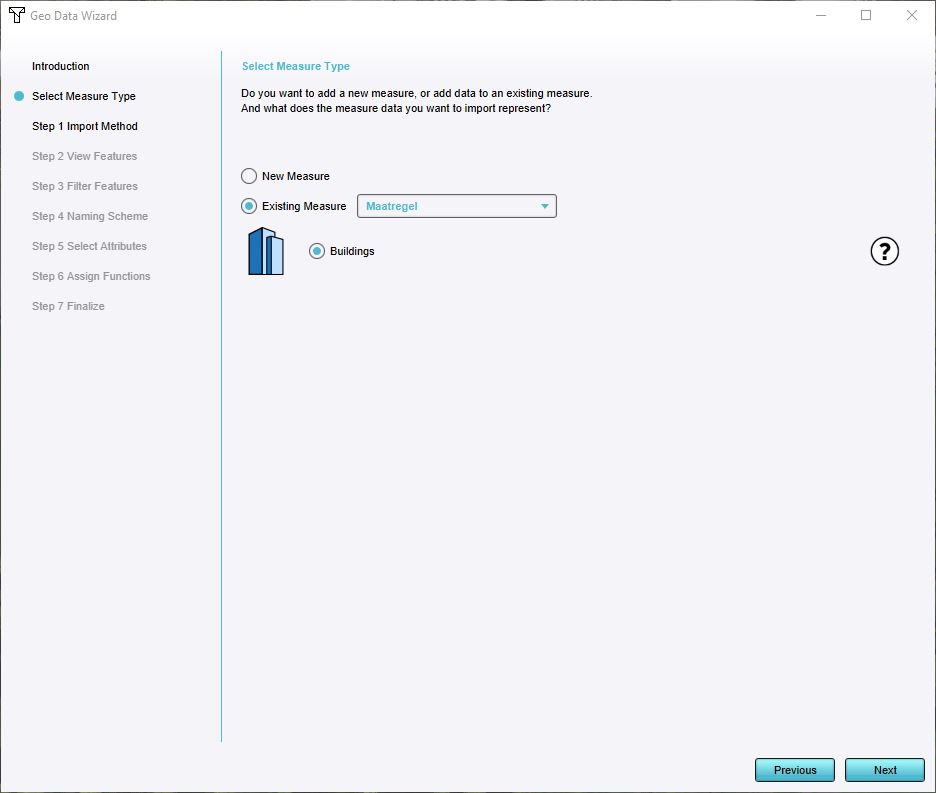 Choose Existing Measure
 -
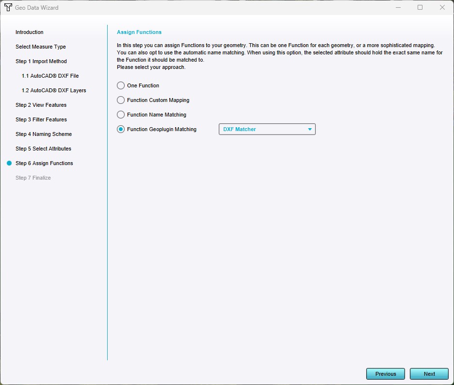 Assign Functions


Adding more elements to the Measure
To demonstrate how variations affect a measure, you can add a soundwall to minimize noise pollution for residents. To achieve this, we will be adding a Spatial based on a GridSpatial to the existing Measure. This means that when the Measure is activated, a new soundwall will be created. This demonstrates how the Tygron Platform combines different data sources within a single measure.
- Click on the Measure that you have created previously. Make sure that the "Test Run" is not active in the upper left part of the screen.
- From the lower menu choose the "Add Grid" option. This will create a new GridSpatial entry with the name GridSpatial 1 as part of your Measure.
- On the Right Editor Panel choose "Add" to fill the entry with a GridSpatial. A selection window appears. Choose "Sound Barrier Combo" from the Overlay selection list. Make sure that the "Sound Barrier Combo" Overlay is inactive". Do this by going to the Overlay menu in the Current Situation and selecting the "Sound Barrier Combo" Overlay and deselecting "Active in Calculation"from the right properties menu.
- Go back to the measure in "Future Design"
- Notice that a soundwall has been raised on the left side below the roundabout. This soundwall will have direct impact when calculating a noise pollution overlay for example. You can visualize this by choosing the Traffic Noise Overlay on the right and switching from 'original' to 'planned' situation in the top left of your project.
- You have now successfully added a new Measure based on DXF data and enriched the Measure with additional Spatial data. You are now ready to analyse your project on different Themes such as Noise pollution.
Explore further
Go to the Main Page and learn more about the different Overlay calculations that can be used on this project. You can find a selection of Overlays under the Calculations Header.
How-to's
- How to import a DXF
- How to predefine the DXF geo-location in AutoCAD
- How to set the unit of measurement for a DXF
- How to create a Geo Plugin to import Buildings from a DXF
- How to deal with a long processing DXF import
- How to add a Grid to a Measure
- How to add a GeoTIFF to a measure
- How to export a DXF
Videos
See also
API Endpoints
- Api session items measures
- Api session event editor measure add grid
- Api session event editor measure add geotiff
- Api session items geoplugins
References
- ↑ original urban plan ∙ Found at: https://dwgmodels.com/642-urban-design.html ∙ (last visited: 20-01-2023)