How to create a parametric design: Difference between revisions
No edit summary |
No edit summary |
||
| (31 intermediate revisions by 6 users not shown) | |||
| Line 1: | Line 1: | ||
[[Parametric | [[Parametric Design]]s are a dynamic means of creating new (urban) developments. Rather than defining a specifically drawn plan as base input, a parametric design is a design which is generated by an algorithm, with a set of parameters as input. | ||
<youtube>2_uBDuVtfMc</youtube> | |||
{{Editor location|parametric design}} | {{Editor location|parametric design}} | ||
{{howto|title=create and use a | |||
| | {{howto|title=create and use a Parametric design| | ||
| | | Click on [[Parametric]] on the [[Future Design]] tab. | ||
| | | On the bottom left of the screen, opt to add a [[Design types (Parametric Design)|Add road aligned]] design, and click "Add". | ||
| | | In the [[left panel]], select the new design. | ||
| | | in the bottom of the [[right panel]], click on 'Draw Area' and select the area for the design. | ||
| | | {{howtoblock| On the ''Design'' tab the overall parameters can be configured: both the percentage and exact [[Function]]s: | ||
| | | Street and Pavement dictate the movement infrastructure. | ||
| | | Buildings dictate the space reserved for actual structures. (The exact [[Function]]s are defined later.) | ||
| | | Parking dictates the space reserved for parking facilities. | ||
| Gardens dictates the typology of the lots around the buildings. Gardens and such. | |||
| Public green dictates separate lots for public utility, like parks or trees. | |||
| Water dictates the addition of water elements to the design. | |||
}} | }} | ||
| {{howtoblock| On the ''Roads'' tab, the structure of the roads can be configured: | |||
| The [[Function]]s of the roads and pavements. | |||
| The dimensions of the roads and pavements. | |||
| The dimensions of the parking spaces. | |||
}} | |||
| {{howtoblock| On the ''Plots'' tab, the [[Function]]s of the building plots are defined: | |||
| New [[Function]]s can be added by clicking on "Add Function". | |||
| Percentage sliders allow for setting how much of the Building spaces should be attributed to that specific [[Function]]. | |||
}} | |||
| {{howtoblock| In the [[left panel]], as sub-items of the design, the building [[Function]]s can be selected to individually configure further: | |||
| The building dimensions can be defined. | |||
| The height, floors, and amount of housing units per building can be defined. | |||
| The spatial fitting parameters can be defined. | |||
}} | |||
| After setting up all the parameters, ensure the design is selected in the [[left panel]]. | |||
| In the [[right panel]], click on "Generate" on the right panel, to generate a plan according to the set parameters. | |||
| {{howtoblock| Verify that the selections in the [[3D Visualization]] and the information in the [[Chart_(Parametric_Design)|pie chart]] look appropriate. | |||
| If not, tweak the parameters further. | |||
}} | |||
| Click on "Apply" to start a [[Test Run]] with the generated design enacted. | |||
}} | |||
{{gallery | |||
|Parametric_011.jpg|1. Click on [[Parametric]] on the [[Future Design]] tab. | |||
|Parametric_012.jpg|2. Add a [[Design_types_(Parametric_Design)|Add road aligned]] design from the dropdown menu. | |||
|Parametric_013.jpg|3. Select the newly added Design. | |||
|Parametric_014.jpg|4. Use 'Draw Area' to select the area for the design. | |||
|Parametric_015.jpg|5. Use sliders to adjust the parameters of the design. | |||
|Parametric_016.jpg|6. Add or change the [[Functions|function types]] on the 'Plots' tab. | |||
|Parametric_017.jpg|7. On the left panel you can remove Function Types. | |||
|Parametric_018.jpg|8. Change function speciffic parameters on the right side. | |||
|Parametric_019.jpg|9. Adjust road speciffic parameters on the 'Roads' tab. | |||
|Parametric_020.jpg|10. Click on 'Generate' to draw the plan according to the set parameters. | |||
|Parametric_021.jpg|11. Verify the planned results and the pie chart. | |||
|Parametric_022.jpg|12. Apply the design in a test run. | |||
|Parametric_023.jpg|13. Verify the actual results, revert if desired. | |||
}} | |||
{{article end | |||
|notes= | |||
* The [[Brush#Polygon_pick|Polygon pick]] selection tool can be especially useful to select predefined areas for designs. | |||
* Especially for road aligned designs it can sometimes be needed to add a road to the area manually in advance, in order to get proper road alignment. | |||
** The {{software}} only adds roads within an area, never on the edge, to avoid adjacent duplicate road placement. | |||
* There are some "pre-designed" configurations available; a City Area, an Urban Area, a Suburban Area, an a Windmill Area. | |||
* Using "Apply" to test the implemented design starts a [[Test Run]]. The generated design is not saved. | |||
** The design can best be saved as a [[Measure]] by using the "Save as Measure" option in the [[right panel]]. This allows the plan to be activated and and reverted freely. | |||
** The design can also be applied directly to the [[Current Situation]]. This makes it part of the base situation of the [[Project area]] and cannot be reversed. | |||
* The fitting margin is a value that allows for smooth rectangular constructions. The smaller the margin is, more of the area is filled with construction, causing all kinds of artifacts. | |||
|seealso= | |||
* [[Parametric Design]] | |||
|howtos= | |||
* [[How to save a parametric design as a measure]] | |||
}} | |||
[[Category:How-to's]] | |||
Latest revision as of 13:57, 30 January 2024
Parametric Designs are a dynamic means of creating new (urban) developments. Rather than defining a specifically drawn plan as base input, a parametric design is a design which is generated by an algorithm, with a set of parameters as input.
- Click on Parametric on the Future Design tab.
- On the bottom left of the screen, opt to add a Add road aligned design, and click "Add".
- In the left panel, select the new design.
- in the bottom of the right panel, click on 'Draw Area' and select the area for the design.
- On the Design tab the overall parameters can be configured: both the percentage and exact Functions:
Street and Pavement dictate the movement infrastructure.
Buildings dictate the space reserved for actual structures. (The exact Functions are defined later.)
Parking dictates the space reserved for parking facilities.
Gardens dictates the typology of the lots around the buildings. Gardens and such.
Public green dictates separate lots for public utility, like parks or trees.
Water dictates the addition of water elements to the design. - On the Roads tab, the structure of the roads can be configured:
The Functions of the roads and pavements.
The dimensions of the roads and pavements.
The dimensions of the parking spaces. - On the Plots tab, the Functions of the building plots are defined:
New Functions can be added by clicking on "Add Function".
Percentage sliders allow for setting how much of the Building spaces should be attributed to that specific Function. - In the left panel, as sub-items of the design, the building Functions can be selected to individually configure further:
The building dimensions can be defined.
The height, floors, and amount of housing units per building can be defined.
The spatial fitting parameters can be defined. - After setting up all the parameters, ensure the design is selected in the left panel.
- In the right panel, click on "Generate" on the right panel, to generate a plan according to the set parameters.
- Verify that the selections in the 3D Visualization and the information in the pie chart look appropriate.
If not, tweak the parameters further. - Click on "Apply" to start a Test Run with the generated design enacted.
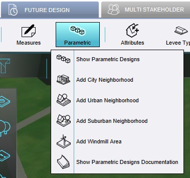
1. Click on Parametric on the Future Design tab.
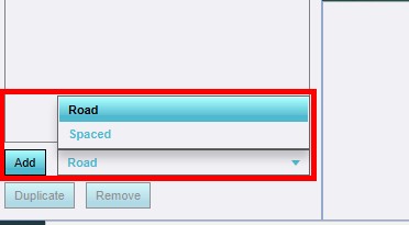
2. Add a Add road aligned design from the dropdown menu.
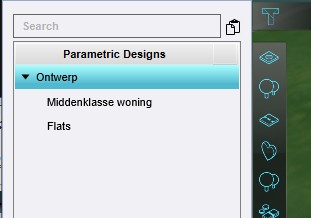
3. Select the newly added Design.
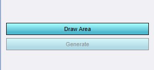
4. Use 'Draw Area' to select the area for the design.
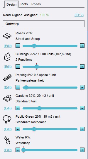
5. Use sliders to adjust the parameters of the design.
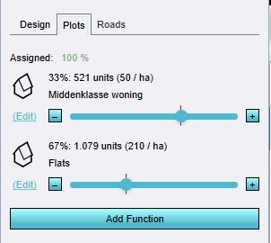
6. Add or change the function types on the 'Plots' tab.
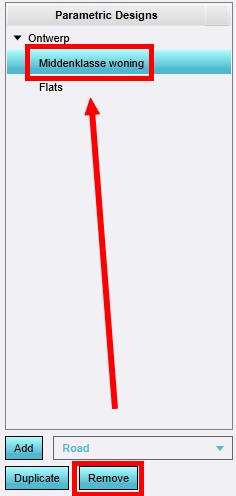
7. On the left panel you can remove Function Types.
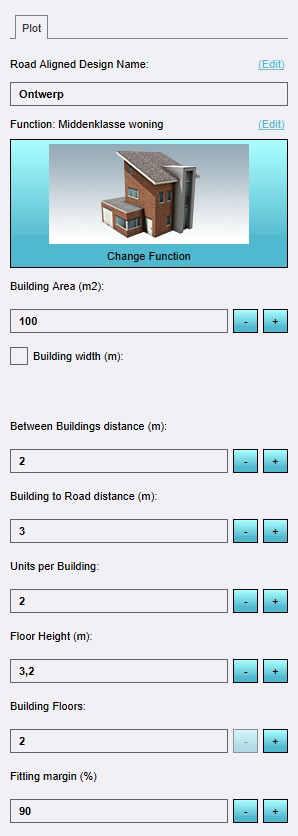
8. Change function speciffic parameters on the right side.
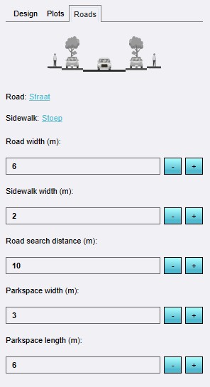
9. Adjust road speciffic parameters on the 'Roads' tab.
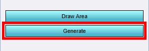
10. Click on 'Generate' to draw the plan according to the set parameters.
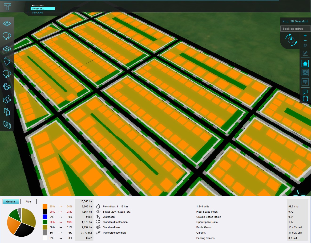
11. Verify the planned results and the pie chart.
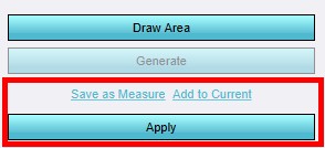
12. Apply the design in a test run.
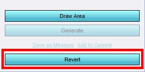
13. Verify the actual results, revert if desired.


Notes
- The Polygon pick selection tool can be especially useful to select predefined areas for designs.
- Especially for road aligned designs it can sometimes be needed to add a road to the area manually in advance, in order to get proper road alignment.
- The Tygron Platform only adds roads within an area, never on the edge, to avoid adjacent duplicate road placement.
- There are some "pre-designed" configurations available; a City Area, an Urban Area, a Suburban Area, an a Windmill Area.
- Using "Apply" to test the implemented design starts a Test Run. The generated design is not saved.
- The design can best be saved as a Measure by using the "Save as Measure" option in the right panel. This allows the plan to be activated and and reverted freely.
- The design can also be applied directly to the Current Situation. This makes it part of the base situation of the Project area and cannot be reversed.
- The fitting margin is a value that allows for smooth rectangular constructions. The smaller the margin is, more of the area is filled with construction, causing all kinds of artifacts.