How to create a parametric design: Difference between revisions
Jump to navigation
Jump to search
No edit summary |
No edit summary |
||
| Line 1: | Line 1: | ||
{{Editor location|parametric design}} | {{Editor location|parametric design}} | ||
{{howto|title=create and use a Parametric design| | {{howto|title=create and use a Parametric design| | ||
| Click on the [[Future Design]] tab | | Click on [[Parametric]] on the [[Future Design]] tab. | ||
| | | On the bottom left of the screen, select to add a [[Design_types_(Parametric_Design)|Add road aligned]] design from the dropdown menu. | ||
| | | On the [[left panel]] a new Design is added. Select this design. | ||
| | | On the bottom right panel, click on 'Draw Area' and select the area for the design. | ||
| | | With the sliders on the 'Design' tab you can adjust the parameters of the design. | ||
| | | On the 'Plots' tab you can add or change the [[Functions|function types]] being used to fill the plots. These will appear also on the left side, under the design you just created. | ||
| | | To remove a function type, you can select the entry on the left side, and click on the 'Remove' button. | ||
| Verify that the selections in the [[3D world]] and the information in the [[Chart_(Parametric_Design)|pie chart]] look like the desired result. If not, tweak the parameters | | You can also change function speciffic parameters on the right side, when you have the function type selected under the design on the left panel. | ||
| Either apply the design to start a [[Test Run]], click on Save to Current to construct the Design in the [[Current Situation]] or save the design as a [[Measure]]. | | On the 'Roads' tab you can adjust road speciffic parameters. | ||
| Verify that the result is correct. If not, revert the application by clicking on Revert | | After setting up all the parameters, click on 'Generate' on the right panel, to draw the plan according to the set parameters. | ||
| Verify that the selections in the [[3D world]] and the information in the [[Chart_(Parametric_Design)|pie chart]] look like the desired result. If not, tweak the parameters further. | |||
| Either apply the design to start a [[Test Run]], click on Save to Current to construct the Design in the [[Current Situation]], or save the design as a [[Measure]]. | |||
| Verify that the result is correct. If not, revert the application by clicking on 'Revert' and tweak the configuration further. Please note that this step is not possible when the design is saved to Current. | |||
}} | }} | ||
<gallery> | |||
File:Parametric_011.jpg|1. Click on [[Parametric]] on the [[Future Design]] tab. | |||
File:Parametric_012.jpg|2. Add a [[Design_types_(Parametric_Design)|Add road aligned]] design from the dropdown menu. | |||
File:Parametric_013.jpg|3. Select the newly added Design. | |||
File:Parametric_014.jpg|4. Use 'Draw Area' to select the area for the design. | |||
File:Parametric_015.jpg|5. Use sliders to adjust the parameters of the design. | |||
File:Parametric_016.jpg|6. Add or change the [[Functions|function types]] on the 'Plots' tab. | |||
File:Parametric_017.jpg|7. On the left panel you can remove Function Types. | |||
File:Parametric_018.jpg|8. Change function speciffic parameters on the right side. | |||
File:Parametric_019.jpg|9. Adjust road speciffic parameters on the 'Roads' tab. | |||
File:Parametric_020.jpg|10. Click on 'Generate' to draw the plan according to the set parameters. | |||
File:Parametric_021.jpg|11. Verify the planned results and the pie chart. | |||
File:Parametric_022.jpg|12. Apply the design in a test run, save to Current , or save as a Measure. | |||
File:Parametric_023.jpg|13. Verify the actual results, revert if desired. | |||
</gallery> | |||
<!-- | |||
<li style = "display:inline-block">[[File:Parametric_001.jpg|100xpx]]</li> | <li style = "display:inline-block">[[File:Parametric_001.jpg|100xpx]]</li> | ||
<li style = "display:inline-block">[[File:Parametric_002.jpg|100xpx]]</li> | <li style = "display:inline-block">[[File:Parametric_002.jpg|100xpx]]</li> | ||
| Line 24: | Line 41: | ||
<li style = "display:inline-block">[[File:Pie_chart.PNG|100xpx]]</li> | <li style = "display:inline-block">[[File:Pie_chart.PNG|100xpx]]</li> | ||
<li style = "display:inline-block">[[File:Parametric_008.jpg|100xpx]]</li> | <li style = "display:inline-block">[[File:Parametric_008.jpg|100xpx]]</li> | ||
--> | |||
===Notes=== | ===Notes=== | ||
* Save to current: a [[Test_Run|test run]] is not started. Instead it is applied to the [[Current Situation]]. This method is not easily reversed. | * Save to current: a [[Test_Run|test run]] is not started. Instead it is applied to the [[Current Situation]]. This method is not easily reversed. | ||
| Line 32: | Line 49: | ||
* [[Parametric Design]] | * [[Parametric Design]] | ||
* [[How to save a parametric design as a measure]] | * [[How to save a parametric design as a measure]] | ||
Revision as of 13:09, 9 December 2021
Editor → Future Design (Ribbon tab) → Parametric (Ribbon bar) → The Parametric Design to edit (Left panel)
How to create and use a Parametric design:
- Click on Parametric on the Future Design tab.
- On the bottom left of the screen, select to add a Add road aligned design from the dropdown menu.
- On the left panel a new Design is added. Select this design.
- On the bottom right panel, click on 'Draw Area' and select the area for the design.
- With the sliders on the 'Design' tab you can adjust the parameters of the design.
- On the 'Plots' tab you can add or change the function types being used to fill the plots. These will appear also on the left side, under the design you just created.
- To remove a function type, you can select the entry on the left side, and click on the 'Remove' button.
- You can also change function speciffic parameters on the right side, when you have the function type selected under the design on the left panel.
- On the 'Roads' tab you can adjust road speciffic parameters.
- After setting up all the parameters, click on 'Generate' on the right panel, to draw the plan according to the set parameters.
- Verify that the selections in the 3D world and the information in the pie chart look like the desired result. If not, tweak the parameters further.
- Either apply the design to start a Test Run, click on Save to Current to construct the Design in the Current Situation, or save the design as a Measure.
- Verify that the result is correct. If not, revert the application by clicking on 'Revert' and tweak the configuration further. Please note that this step is not possible when the design is saved to Current.
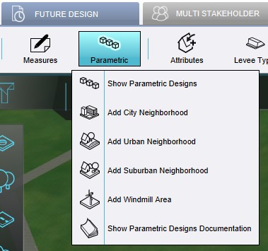
1. Click on Parametric on the Future Design tab.
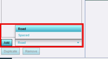
2. Add a Add road aligned design from the dropdown menu.
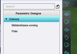
3. Select the newly added Design.
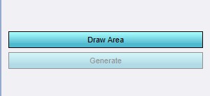
4. Use 'Draw Area' to select the area for the design.
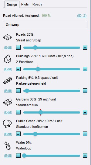
5. Use sliders to adjust the parameters of the design.
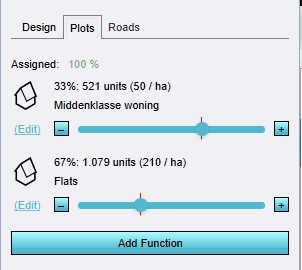
6. Add or change the function types on the 'Plots' tab.
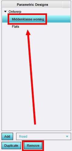
7. On the left panel you can remove Function Types.
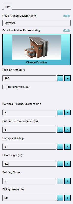
8. Change function speciffic parameters on the right side.
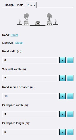
9. Adjust road speciffic parameters on the 'Roads' tab.
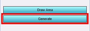
10. Click on 'Generate' to draw the plan according to the set parameters.
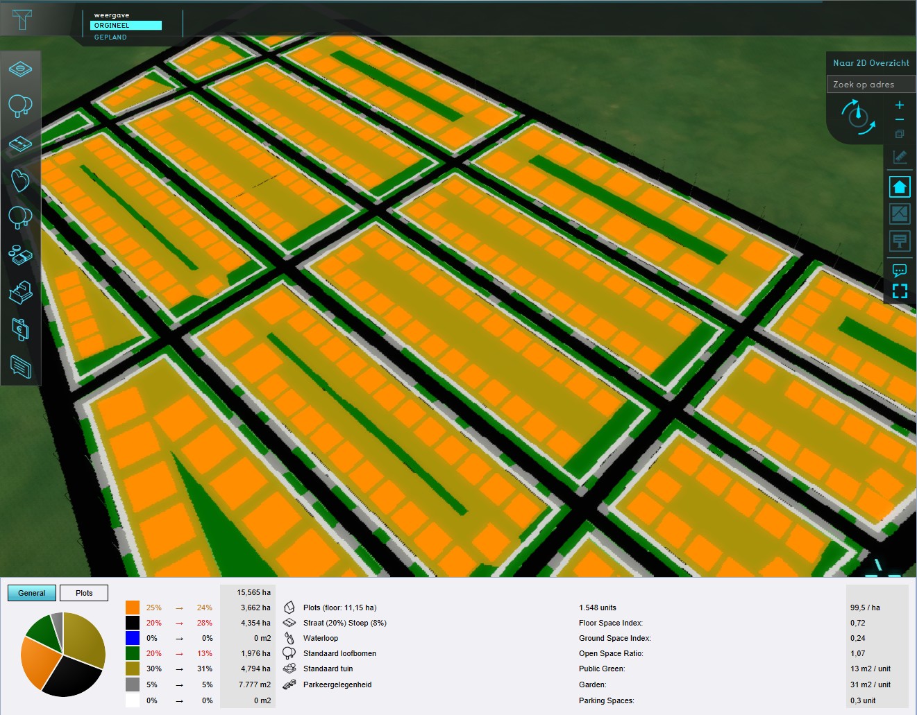
11. Verify the planned results and the pie chart.
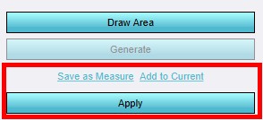
12. Apply the design in a test run, save to Current , or save as a Measure.
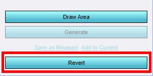
13. Verify the actual results, revert if desired.


Notes
- Save to current: a test run is not started. Instead it is applied to the Current Situation. This method is not easily reversed.
- Tip: use the Polygon pick selection tool to draw the area for the design.