Line-based building (Water Overlay): Difference between revisions
No edit summary |
|||
| Line 56: | Line 56: | ||
*The length of the polygon along the line should be longer than the width of the polygon perpendicular to the line. | *The length of the polygon along the line should be longer than the width of the polygon perpendicular to the line. | ||
{{article end | |||
*[https://en.wikipedia.org/wiki/Topological_skeleton Topological skeleton] | |seealso= | ||
* [https://en.wikipedia.org/wiki/Topological_skeleton Topological skeleton] | |||
|api= | |||
* [[Api session items buildings]]. | |||
}} | |||
{{Water Module buttons}} | {{Water Module buttons}} | ||
Revision as of 10:19, 7 July 2026
Line-based buildings are Buildings for which their geometry is interpreted as a 2 dimensional line with two end points.
Examples of line-based buildings are the following hydraulic structures:
| Icon | Name | Name |
|---|---|---|

|
Culvert | Flow in both directions possible. |

|
Weir | Conditional flow, based on the weir's height. Flow possible in both ways. |

|
Pump | Pumps water from the entry with the lowest water level to the entry with the highest water level. |
Polygon skeleton
A method to obtain line geometries from a polygonal geometry is called topological skeletonization. In the case of Line-based buildings, we want to obtain only a single line segment. Currently only a simple implementation is used:
- Skeletonize a building's polygon. This potentially produces a multi-line geometry.
- Take the first point and the last point of this line geometry. These two points will form the line segment used for the line-based building.

The method above is simple, but not robust in all cases. See the following images:
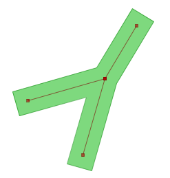
Case one: Polygon with skeleton that has 3 end points. 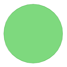
Case two: Circle polygon without any end points. 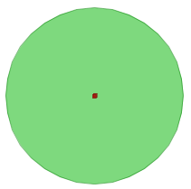
Case three: Almost circular polygon with very small skeleton.


In case one, the resulting skeleton lines have 3 different end points. Which of these points will be the first and last end point is dependent on the sequence of coordinates in the polygon.
In case two, the polygon is a perfect circle, resulting in no skeleton line.
In case three, the skeleton line is very small, for example 1 centimeter. This may not be desirable when the end points need to be separated more than a certain amount.
More complex but common situation:
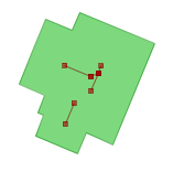
Skeleton of semi-complex building polygon. 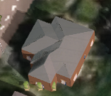
Resulting roof from building polygon and skeleton.


Generally, this kind of polygon is undesirable for a line-based building, since it will generate a skeleton with many end points.
Direction
For some structures, a direction is relevant to determine from which location (A) to which location (B) water flows, and to relate any output attributes related to properties on either side of the Building. Particular types of structures may have their own rules for determining their "direction" as such. If those rules are absent (such as for a culvert), or unclear (such as based on higher of 2 water levels, but both water levels are the same), the direction is determined based on the computed skeleton line of the structure.
The Tygron Client displays the endpoint names (A, B) when you enable the Water Overlay and zoom into the structure location. Whether A or B corresponds to a specific side is determined by the structure’s skeleton line and can be retrieved via the Building API. The first coordinate represents side A, and the last coordinate represents side B.
General advice
- The line-based buildings should be supplied as rectangles or line-buffered polygons.
- The length of the polygon along the line should be longer than the width of the polygon perpendicular to the line.