Elevation model: Difference between revisions
No edit summary |
|||
| Line 5: | Line 5: | ||
The elevation model (also referred to as DEM) in the {{software}} is a 2-dimensional grid with values indicating the terrain height in meters relative to {{datum}}. [[Terrain]] in this context meaning the soil and the subsurface. | The elevation model (also referred to as DEM) in the {{software}} is a 2-dimensional grid with values indicating the terrain height in meters relative to {{datum}}. [[Terrain]] in this context meaning the soil and the subsurface. | ||
The [[3D World]] visualizes the elevation model inherently as the bottom plane upon which all other features, such as [[ | The [[3D World]] visualizes the elevation model inherently as the bottom plane upon which all other features, such as [[building]]s, are placed. Changes in terrain height are similarly changes in the height of that plane. | ||
In the {{software}}, the elevation model offers terrein heights representation as both a [[Digital Terrain Model Overlay|DTM (Digital Terrain Model)]] and as a [[Digital Surface Model Overlay|DSM (Digital Surface Model)]]. A DTM represents the bare ground surface without any objects like plants and buildings. In contrast; a DSM represents the earth's surface including all objects (e.g. houses, trees, etc.) on it. This means features such as [[ | In the {{software}}, the elevation model offers terrein heights representation as both a [[Digital Terrain Model Overlay|DTM (Digital Terrain Model)]] and as a [[Digital Surface Model Overlay|DSM (Digital Surface Model)]]. A DTM represents the bare ground surface without any objects like plants and buildings. In contrast; a DSM represents the earth's surface including all objects (e.g. houses, trees, etc.) on it. This means features such as [[building]]s are explicitly not a part of the DTM, but are a part of the DSM. In locations with [[Water (Terrain Attribute)|water]], the elevation model follows the bottom of the water body for both the DTM and the DSM. | ||
The [[3D World]] visualizes the elevation model inherently as the bottom plane upon which all other features, such as [[ | The [[3D World]] visualizes the elevation model inherently as the bottom plane upon which all other features, such as [[building]]s, are placed. Changes in terrain height are similarly changes in the height of that plane. | ||
The elevation model consists of a single dataset, which is generated when a [[Project]] is first created. Any changes to the elevation model are applied directly to that dataset, including [[manually drawn changes]] as well as [[imported changes]]. | The elevation model consists of a single dataset, which is generated when a [[Project]] is first created. Any changes to the elevation model are applied directly to that dataset, including [[manually drawn changes]] as well as [[imported changes]]. | ||
| Line 66: | Line 66: | ||
** Crop fields/agriculture | ** Crop fields/agriculture | ||
===DSM ( | ===DSM (building height)=== | ||
For [[ | For [[building]]s, the average height of the AHN DSM is determined for the polygon defining the [[building]]'s footprint.That average height of the AHN DSM is then determined to be the height of the [[building]]. | ||
Using image recognition techniques, the footprint polygon of the [[ | Using image recognition techniques, the footprint polygon of the [[building]]s may be split into multiple [[Building section]]s, each with their own polygon. The AHN DSM's average height is then determined per individual section, so that the variability in the rooftops of the [[building]] can be taken into account. | ||
The resulting [[ | The resulting [[building]] heights are not made part of the DTM. Instead, they are stored as properties of the [[building]]s in the [[Project]]. | ||
===Water=== | ===Water=== | ||
| Line 104: | Line 104: | ||
|} | |} | ||
For the DSM height, the heights of [[ | For the DSM height, the heights of [[building]]s are used. If available, the {{Project source|OSM}} building heights are used, otherwise the default heights. The default heights differ per [[Function|function]], based on the [[Default_floors_(Function_Value)|default floors]] and [[Floor_height_m_(Function_Value)|floor height]]. | ||
==Data format== | ==Data format== | ||
Revision as of 15:28, 7 October 2022
An elevation model (or DEM, Digital Elevation Model), is a model representation of terrain heights; the quantitative measurement of vertical elevation change in a landscape. On a small scale, differences in terrain height can affect shade and water distribution. On a larger scale, terrain height has an effect on weather and climate patterns.
Implementation in the Tygron Platform
The elevation model (also referred to as DEM) in the Tygron Platform is a 2-dimensional grid with values indicating the terrain height in meters relative to datum. Terrain in this context meaning the soil and the subsurface.
The 3D World visualizes the elevation model inherently as the bottom plane upon which all other features, such as buildings, are placed. Changes in terrain height are similarly changes in the height of that plane.
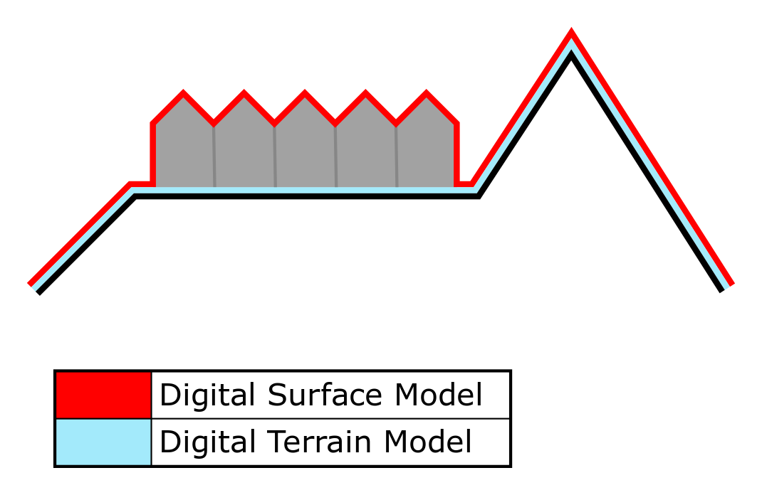
In the Tygron Platform, the elevation model offers terrein heights representation as both a DTM (Digital Terrain Model) and as a DSM (Digital Surface Model). A DTM represents the bare ground surface without any objects like plants and buildings. In contrast; a DSM represents the earth's surface including all objects (e.g. houses, trees, etc.) on it. This means features such as buildings are explicitly not a part of the DTM, but are a part of the DSM. In locations with water, the elevation model follows the bottom of the water body for both the DTM and the DSM.
The 3D World visualizes the elevation model inherently as the bottom plane upon which all other features, such as buildings, are placed. Changes in terrain height are similarly changes in the height of that plane.
The elevation model consists of a single dataset, which is generated when a Project is first created. Any changes to the elevation model are applied directly to that dataset, including manually drawn changes as well as imported changes.
Elevation model generation
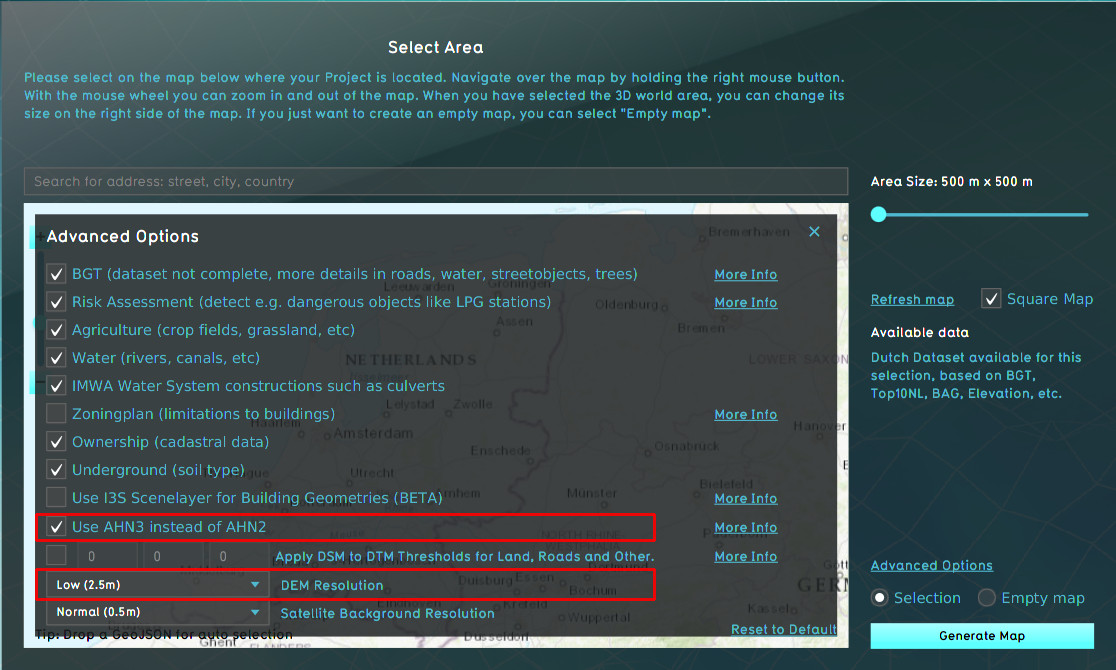
The elevation model is generated when a Project is first created. The advanced options allow you to select the used data sources and resolution for the elevation model.

In the Netherlands, the following data sources are used to construct the elevation model:
| Name | Resolution | Description | Source |
|---|---|---|---|
| ESRI DTM | 3m by 3m | Dataset supplied by Rijkswaterstaat to ESRI, based on AHN2. | https://www.arcgis.com/home/item.html?id=58a541efc59545e6b7137f961d7de883 |
| AHN DSM | 0.5m by 0.5m, 1m by 1m, or 2.5m by 2.5m, depending on selected options. | Raw data from Actueel Hoogte Bestand | |
| AHN DTM | 0.5m by 0.5m, 1m by 1m, or 2.5m by 2.5m, depending on selected options. | Interpolated (surface level) data based on Actueel Hoogte Bestand | |
| Features | Presence of features of the built environment | https://www.pdok.nl/introductie/-/article/basisregistratie-grootschalige-topografie-bgt- (BGT) and https://www.pdok.nl/introductie/-/article/basisregistratie-topografie-brt-historie (Top10NL) |
- By default the AHN3 is used for the DTM and DSM. AHN2, AHN3, or AHN4 can be selected.
- If AHN4 is used in a location where coverage is incomplete, no fallback data will be available which means data will be missing in that part of the project.
- By default the BGT is used for the features in the 3D World. If the BGT is deactivated in the advanced options panel, TOP10NL is used.
DTM (Terrain height)
The DTM is generated as follows:
- The ESRI DTM is resampled to the same resolution as the AHN DTM and AHN DSM.
- The AHN DTM serves as the base data for the resulting elevation model DTM.
- In locations where the AHN DTM has NO_DATA values (such as waterbodies), the ESRI DTM is used.
- Optionally, if the option for applying thresholds is selected, the AHN DSM heights are used instead of the so far determined DTM heights, if the difference between the two does not exceed a certain threshold. The following features can have the DSM heights applied instead:
- Bare land
- Roads
- Crop fields/agriculture
DSM (building height)
For buildings, the average height of the AHN DSM is determined for the polygon defining the building's footprint.That average height of the AHN DSM is then determined to be the height of the building.
Using image recognition techniques, the footprint polygon of the buildings may be split into multiple Building sections, each with their own polygon. The AHN DSM's average height is then determined per individual section, so that the variability in the rooftops of the building can be taken into account.
The resulting building heights are not made part of the DTM. Instead, they are stored as properties of the buildings in the Project.
Water
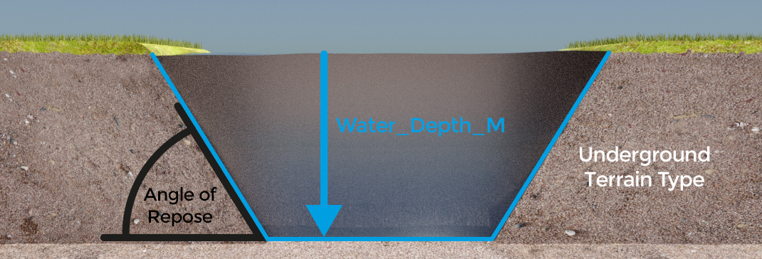
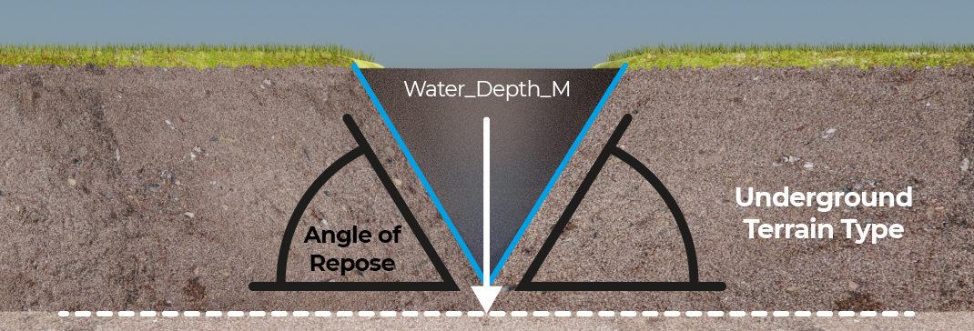
Water bodies, found in terrain surface types, are lowered a few meters relative to the elevation of the surrounding surface. The following parameters are used:
- The default water depth of the determined Terrain Type of the waterbody is used.
- The angle of repose of the Underground Terrain Type present at or near the sides of the waterbodies.
From the DTM a point is selected at the waterbody's edge, or as close as possible. The Angle of repose value of the underground Terrain Type present in that point is determined. A downward slope is created at the determined angle of repose. The downward slope continues until either it meets the slope generated from the other end, or it reaches the determined default water depth relative to the DTM. This means that thin waterways will not be as deep as their default water depth allows them to be, and that large water bodies are likely to have flat water bottoms.
The resulting terrain height changes are made part of the DTM.
To improve the water depth with your own data, see:
Elevation model generation (outside the Netherlands)
For the elevation model in projects abroad, the ESRI DTM is used. The resolution differs per location, based on the used data sources for creating the ESRI DTM layer.
| Name | Resolution | Description | Source |
|---|---|---|---|
| ESRI DTM | Differs per location, see the metadata for more information | Ground height dataset of ESRI, based on multiple sources. | https://www.arcgis.com/home/item.html?id=58a541efc59545e6b7137f961d7de883 |
For the DSM height, the heights of buildings are used. If available, the OSM building heights are used, otherwise the default heights. The default heights differ per function, based on the default floors and floor height.
Data format
The height is stored in Height sectors, which are square 500m x 500m tiles floating point values which store the height data in meters, with a precision of 3 decimals. The amount of points per height sector depend on the DEM resolution configured in advanced options of the New Project Wizard, before project creation, and cannot be increased or decreased later on.
Heightmap Overlays
More insight into the elevation model can be provided by adding the Digital Terrain Model Overlay or the Digital Surface Model Overlay, which are grid overlays showing the (average) height per grid cell. The amount of averaging depends on the configured grid cell size.
How-to's
- How to change how the default elevation model is generated
- How to import a GeoJSON to change the elevation model
- How to import a GeoTIFF to change the elevation model
- How to import a GeoJSON of waterways
- How to import a GeoTIFF of waterway depths
- How to use the terrain height brush in selection mode
- How to use the terrain height brush in live sculpting mode
- How to export the elevation model


