Culvert formula (Water Overlay): Difference between revisions
Jump to navigation
Jump to search


mNo edit summary |
mNo edit summary |
||
| Line 32: | Line 32: | ||
* B<sub>c</sub> = The [[Terrain height (Water Overlay)|surface height]] of the base of the culvert. | * B<sub>c</sub> = The [[Terrain height (Water Overlay)|surface height]] of the base of the culvert. | ||
* w<sub>left</sub> = The [[Surface water level formula (Water Overlay)|water level]] on the left side of the culvert, relative to {{datum}}. | * w<sub>left</sub> = The [[Surface water level formula (Water Overlay)|water level]] on the left side of the culvert, relative to {{datum}}. | ||
* w<sub>right</sub> = The Surface water level formula (Water Overlay)|water level]] on the right side of the culvert, relative to {{datum}}. | * w<sub>right</sub> = The [[Surface water level formula (Water Overlay)|water level]] on the right side of the culvert, relative to {{datum}}. | ||
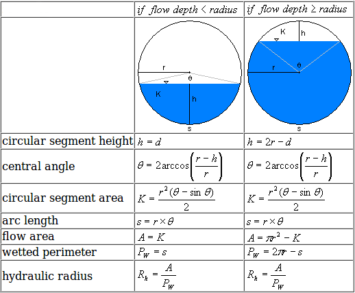
* R<sub>h</sub> = The hydraulic radius in the culvert<ref name="hydradius"/>. | * R<sub>h</sub> = The hydraulic radius in the culvert<ref name="hydradius"/>. | ||
* K = Flow area, based on the height of the water in the (circular) culvert. | * K = Flow area, based on the height of the water in the (circular) culvert. | ||
Revision as of 08:26, 14 June 2019


Flow through culverts is based on an open channel flow calculation.
The actual height of the culvert is at least the height of the terrain on either end of the culvert and the provided threshold height:
- Bc = max( Tc , Bl , Br )
The radius of the culvert:
- r = D / 2.
The height of the water column at either end of the culvert, relative to the culvert, is calculated:
- wl = max(0, wl - Bc)
- wr = max(0, wr - Bc)

Flow depth d is:
- d = max ( 0 , min ( D , max ( wl , wr ) - Bc ) ) )
The loss coefficient for the culvert is calculated:
- U = sqrt( 1 / ( 1 + 2 * g * n2 * length / Rh4/3 ) )
The hydraulic radius Rh is calculated using the formula's in the image on the right.
The potential flow through the culvert is then calculated:
- C = U * K * sqrt( 2 * g * abs( wl - wr ) )
Finally the actual amount of water flow is calculated:
- Δf = Δt * C / Δx
Where:
- D = The CULVERT_DIAMETER attribute of the culvert.
- Tc = The CULVERT_THRESHOLD attribute of the culvert.
- Bc = The surface height of the base of the culvert.
- wleft = The water level on the left side of the culvert, relative to datum.
- wright = The water level on the right side of the culvert, relative to datum.
- Rh = The hydraulic radius in the culvert[1].
- K = Flow area, based on the height of the water in the (circular) culvert.
- g = Acceleration factor of GRAVITY, defined for the Water Overlay.
- L = The length of the culvert, calculated as the distance between the culvert's endpoints.
- U = Loss coefficient for culverts.
- n = The CULVERT_N attribute of the culvert.
- C = The potential rate of water flow through the culvert.
- Δf = The water flow which takes place.
- Δt = Computational timestep.
- Δx = Cell size.
See also
References
- ↑ Hydraulic Radius Equations Formulas Calculator ∙ found at: https://www.ajdesigner.com/phphydraulicradius/hydraulic_radius_equation_pipe.php ∙ (last visited 2019-02-11)