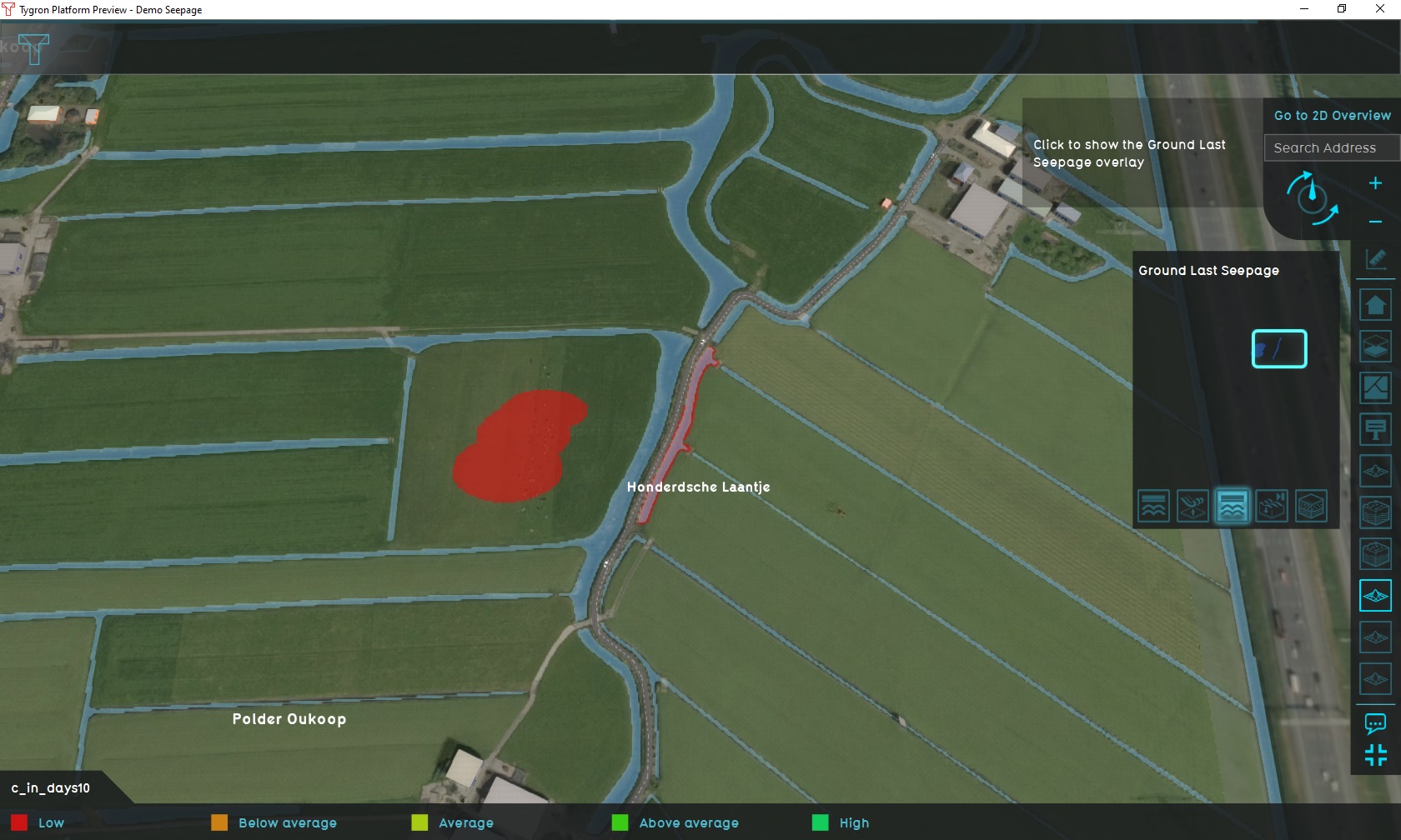
Demo Seepage Project
| Next page>> |
The Demo Seepage project is available for all users and can be found in the main menu under Edit projects. This project does not count towards your license.
This project is intended for hydrologists and other water experts.
This project showcases the seepage functionality.
In this project a location in The Netherlands, Polder Oukoop, is experiencing seepage.
It can serve as a working demo to explore the Seepage functionality and the configurable parameters.The following steps below show how seepage calculations with different parameters highlight the different ways seepage can be configured and varied.
Exploring the project
To begin exploring the project, take the following steps:
- Click anywhere in the 3D world, and use the arrow keys on your keyboard to move around in the world. You can also drag the camera around by right-clicking (and holding the right mouse button down) in the 3D world and dragging the world around. Use the scroll wheel to zoom in- and out.
- On the right-hand side of the 3D world you can see the overlays menubar. Hover over the various icons to see a tooltip with their name. Find the overlay named "Groundwater (spatial)", and click on it. This will show the overlay in the 3D world. This overlay shows the groundwater level in the underground.
- At the bottom of the interface a legend will now appear, with on the left-hand side of the legend a few buttons to "play" the overlay. Click on the "play" button, and you will see how the state of the groundwater level changes over time.
- Hover over the icon for the overlay again, and notice that more options appear for overlays related to groundwater. These are the child overlays, which can display more types of results from the groundwater simulation.
- Notice multiple Overlays exist, each showing a specific result or type of data related to seepage:
- The "Groundwater (Spatial)" Overlay calculates and shows the result for the seepage calculation, with a static amount of pressure and resistance affecting the groundwater levels, without any configured fluctuation.
- The "Groundwater (Fluctiation)" Overlay calculates and shows the results for a seepage calculation, in which natural pressure and resistance are configured to limit base seepage, so that the effect of seepage fluctuation is more visibly demonstrated.
- A GeoTiff Overlay showing spatial seepage pressures. It has two child Overlays demonstrating the configuration for resistance values of 10 days, and the resistance values of 500 days.
- Finally, notice a number of icons floating in the world. The orange icons are of particular note; these denote points-of-interest which you can take a closer look at. You can click on any to open a panel with more information.
Overlay configurations
There are two Overlays which demonstrate two separate inputs for seepage in a Water Overlay. Both are the same calculation model, just with different seepage parameters configured. For either Overlay, it's seepage configuration can be reviewed in their respective configuration wizards.
Groundwater (Spatial)
This Overlay has been configured to only make use of the spatial parameters for seepage, meaning the amount of seepage varies between locations but does not change over time. Most of the terrain has a negative resistance, excluding seepage calculations in those locations. There are a few patches where resistance is configured to a rate of a couple of days. Thus, the rate and amount of seepage demonstrated in this Overlay is entirely due to the static (albeit spatially differing) pressures and resistances.
- Static, spatially differing pressures defined by a GeoTiff accessible via the "Seepage pressure locations" Overlay.
- Static, spatially differing resistances defined by a GeoTiff accessible via the "Seepage resistance 10 days" Overlay. In the relevant patches, a resistance value of 10 days allows noticeable seepage to occur over a period of a few days
- No fluctuation in seepage pressure defined, meaning the amount of seepage which occurs remains entirely constant over time.
- The simulation lasts for 2 days.
Groundwater (Fluctuation)
This Overlay has been configured with proper spatial pressure, but excessive resistances in the relevant locations. The amount of seepage occurring due to those parameters is therefor a lot less. However, a fluctuation has also been defined which causes the amount of seepage to be supplemented by a varying amount over time. Thus, the rate and amount of seepage demonstrated in this Overlay is strongly affected by the fluctuation parameter.
- Static, spatially differing pressures defined by a GeoTiff accessible via the "Seepage pressure locations" Overlay.
- Static, spatially differing resistances defined by a GeoTiff accessible via the "Seepage resistance 500 days" Overlay. In the relevant patches, a resistance value of 500 days strongly reduces the amount of seepage.
- The seepage fluctuation parameter starts at a negative value. It increases (but remains negative) after 2 days. 2 days later it becomes high and positive, and during the last 2 days the value is 0. This means the amount of seepage due to fluctuation changes every 2 days.
- The simulation lasts for 8 days.
Points of interest
The project offers a number of points of interest to inspect in greater detail. A number of these points have been emphasized with popups.
Seepage under land
At the location of this popup, underground pressure will cause seepage to occur, slowly increasing the groundwater level.
Select the "Groundwater (Spatial)" Overlay, and play the overlay. As time progresses, the patch of land where seepage occurs will experience a rising groundwater level, until the pressure of the seepage even causes the water to seep onto the surface.
Place a point measurement on the wet patch, and select the "Groundwater (Fluctuation)" Overlay. Play the Overlay. You will see the measurement shows a varying rate at which seepage occurs, dictated by the seepage fluctuation which varies over time. Especially notable is that the groundwater level increase at the start of the simulation (when the fluctuation parameter is negative) is clearly less than at the end of the simulation (when the fluctuation parameter is 0).
Seepage under waterway
At the location of this popup, underground pressure will cause seepage to occur under the waterway.
Place a line measurement along the waterway where seepage occurs, and select the "Surface last value (Spatial)" Overlay. Add as a base Overlay the "Surface elevation (Spatial)" Overlay, and select the "sum" mode. Play the overlay. You will see the initial state of the waterway is a dry waterbed. However, as time and seepage progresses, eventually water will seep up from the underground into the waterway.
Using the same measurement, select the "Groundwater (Fluctuation)" Overlay. Disable the "sum" mode. (You do not need to change the base overlay, as both Overlays share the same elevation model.) Play the overlay. You will see the groundwater level rises at a varying rate, dictated by the seepage fluctuation which varies over time. Especially notable is that the groundwater level increase at the start of the simulation (when the fluctuation parameter is negative) is clearly less than at the end of the simulation (when the fluctuation parameter is 0).
No seepage
In locations with either no resistance or pressure defined, or with negative resistance defined, no seepage occurs. This location can be recognized by this pop up. Both seepage into the project area as well as seepage out of the project area are disabled.
| Next page>> |


