Exporting Blender models to CityJSON
You can import a CityGML file into the Tygron Platform to evaluate 3d city designs. Depending on your own processes, this might require you to export a model from Blender first. Therefore, this article deals with exporting a Blender model to CityJSON so that it can be imported into the Tygron Platform via the CityGML importer. Blender is the free and open source 3D creation suite. To learn more about Blender visit https://www.blender.org/ or https://en.wikipedia.org/wiki/Blender_(software)
In order to export Blender models to CityJSON we first need to install the Up3date exporter and install it as an add-on in to Blender. This add-on was originally developed by Konstantinos Mastorakis (konmast3r) as part of a research orientation project for the MSc Geomatics programme of TU Delft. Its functionality was further developed for the needs of their MSc thesis 'An integrative workflow for 3D city model versioning'.
To read the documentation go to https://github.com/cityjson/Up3date#exporting-a-3d-city-model.
Setting up the exporter in Blender.
1. Visit https://github.com/cityjson/Up3date and download the zip file from the green Code dropdown menu on the right side.
2. Open Blender and go to Edit -> Preferences.
3. In the preference dialog click on "Add-ons". You can see a list of the add-ons which are available for Blender.
4. Click on "Install" in the top right and select the zip file which you have downloaded.
5. After install the exporter will be available in the list. (Import-Export: Import CityGML)
6. Click on the checkbox next to it to activate the exporter.
7. Close the Preferences dialog.
Preparing your model for export
There is a small setup needed in order to export your model succesfully to CityJSON. This consists of naming conventions and custom properties that need to be added to your model and Blender environment. Another important issue is the Levels of Detail that need to be setup. CityGML supports 4 levels, from 0 to 4. 0 is the lowest resolution version of the model. This means the polycount is very small. 4 is the most dense. Levels of Detail are primarily used in real time engines like the Tygron Platform to load the appropriate size model for the particular zoom level. This helps reduce memory when a large area is displayed. In this setup we will be using the Level of Detail 2. For other levels, the workflow is the same. (Consult screenshots for more clarification).
1. Rename your collection (name of the group the model is in) in the outliner to "LoD2" by double clicking on it. Make sure that your model is part of this collection.
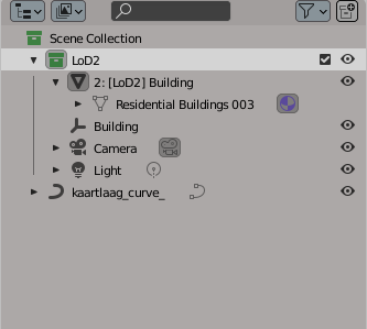
The outliner in Blender.
2. Rename your model to the following specification: 2: [LoD2] ID_of_object. The "2" represents the LoD and "ID-of_object" represents the name of the object. So for example a level 2 house model could be renamed as: 2: [LoD2] Building
3. In the object properties add 2 new custom properties to your model:
- type: the_surface_type (Surface, MultiSurface, CompositeSurface and Solid are accepted)
- lod : the_number_of_lod
So for this example the type would be "Solid" and the lod would be "2"
3.1. To add properties correctly, click on the edit button to configure the attribute.
3.2. Choose from the type dropdown "Integer" if your property will be a whole number. Property name should be in this case "lod". Set the Max value to the value you want the property to have. In this case 2. Click on OK.
3.3. Finally change the value of the new lod to 2 instead of 1.
3.4. For non number values choose "String" as type and name your property in the Property Name field. In this case "type". Click OK and change the value to "Solid".
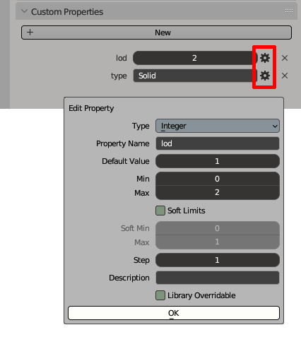
Add object properties.
4. Add an empty object to the Lod2 Collection and rename it to the "ID_of_object". So in this example it would be "Building".
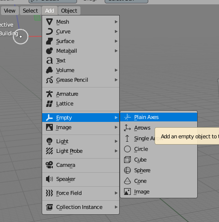
Add empty object.
5. Add a custom property to the empty object: (See step 3.1, choose "String")
- type: Building
You could add more properties to the object as needed such as "address.PostalCode: 0000AB". This depends on what meta information you would like to export with your model.
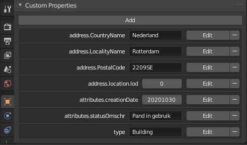
An example of more properties.
6. Finally add a new property to the Environment settings in Blender. Here we will tell the exporter to export the georeference coordinate system which we want. In this example we will be using: CRS:urn:ogc:def:crs:EPSG:28992 (See step 3.1, choose "String")
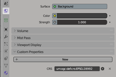
Add environment properties.
7. If you have any materials add a new property to the material under the custom properties section in the materials tab. Make sure you have the material selected. If you have multiple materials add custom properties to these as well. You can choose the following: type: Semantic_name (WallSurface, RoofSurface, GroundSurface) So for this example we will use only Wallsurface and add the property as this: type:WallSurface. (See step 3.1, choose "String")
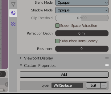
Add material property
Georeference your model
One of the issues when dealing with non-GIS based 3d modelling software is the absence of any Georeference systems. This means that a model exists only in "Blender" local space and not necessarily in an geographic location. Most reference systems work with degrees and not with metric or imperial units. So how do we know where our model should be located when exporting it from Blender with the correct reference system? Remember we used in this example the CRS:urn:ogc:def:crs:EPSG:28992 system. To fix the location we will need different GIS enabled software to help us out. In this example we will be using QGIS which is an open source package which handles georeferencing with ease. To download QGIS go to: https://qgis.org/en/site/
This walkthrough assumes you have some knowledge with QGIS.
1. Make a new project in QGIS.
2. Connect to a WMS service and choose the background map which should be shown.
3. Make sure you choose the "Amersfoort / RD New" "EPSG:28992" Reference System for use with this example by going to project settings and choosing the right system in the CRS tab. If you use a different system make sure that the system is added as a property in step 6 of "preparing your model for export" (This will correspond with the system we have added as a property to the Blender Environment, namely: CRS:urn:ogc:def:crs:EPSG:28992).
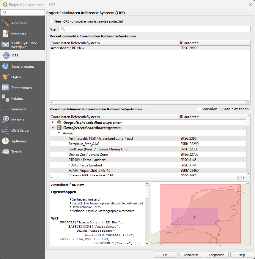
CRS settings.(Search for the System if you do not see it in the list)
4. Add a new shapefile layer and choose LineString as mode of drawing.
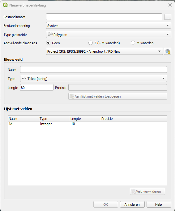
Add new shapefile layer.
5. Activate the Edit setting (The yellow pencil icon) and add a new object. This will start Line drawing on the map.
6. Draw a square or any shape to outline where your 3d model should ultimately fit in the location. We will use this Line as a reference in Blender to move our 3d object on to.
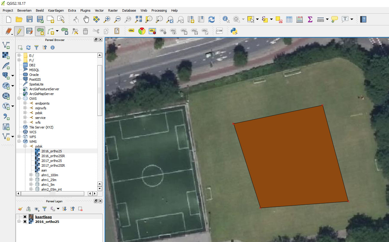
Draw polygon
7. Click on the save edit icon next to the edit object icon (yellow pencil). This will save any edits for this object. Note that this is a different save than the normal file save.

Edit tools.
8. Right Click on the map layer and choose export. In the dialog select "DXF" als export format and make sure that the "Amersfoort / RD New" "EPSG:28992" reference is used. Save it somewhere on your harddrive.
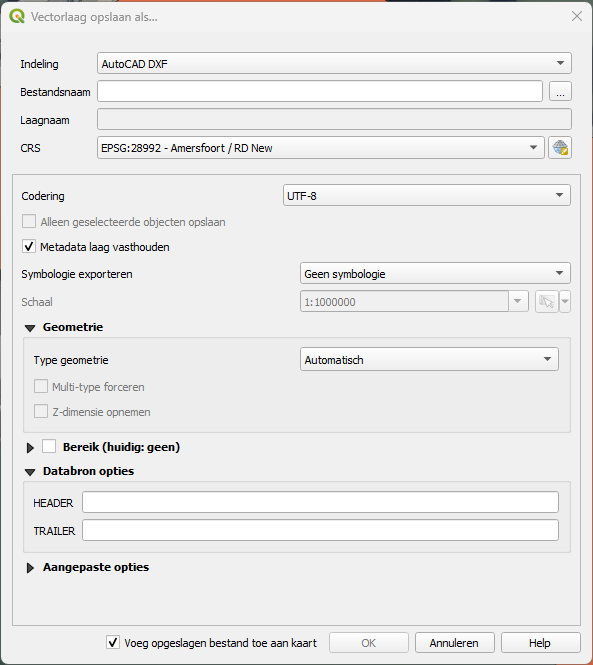
Export to DXF.
9. Go to Blender and select import from the file menu and choose AutoCAD DXF. If you do not have DXF importer installed for Blender just go to the addons and search for DXF. Select the checkbox to activate it.
10. The Line drawing is imported in to Blender and now we know the location of the area we want our building to be in.
11. Move the Building model on top of the drawing. The drawing will probably be very far away in Blender space which will make the viewport act very funny, so you could paste the x and y coordinates from the polygon to the building to make it easier. Remember to set the origin of the drawing to the geometry. To do this, select the drawing and right click on the viewport. Select "set origin" from the context menu and choose "Origin to geometry". This will make the center point move to the drawing object. Now the x and y coordinates correspond to where the drawing is.
12. Finally, select the building and export it to CityJSON (.json). This file is ready to be imported in to the Tygron Platform by way of importing buildings with the Geo Wizard and choosing CityGML as import option.
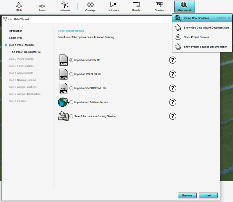
Import building as GeoJSON via Geo import button.