Ground flow formula (Water Overlay): Difference between revisions
Jump to navigation
Jump to search
No edit summary |
No edit summary |
||
| Line 2: | Line 2: | ||
===Default horizontal flow=== | ===Default horizontal flow=== | ||
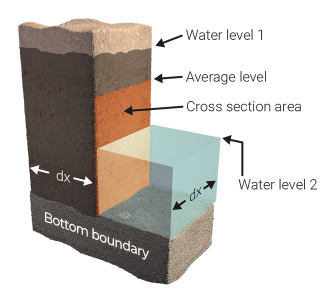
[[File:Undergroundflow2. | [[File:Undergroundflow2.png|right|400px|thumb|Two adjacent cells, where underground water level of cell 1 is larger than cell 2.]] | ||
The flow between the two cells is calculated as: | The flow between the two cells is calculated as: | ||
: Δw = w<sub>1</sub> - w<sub>2</sub> | : Δw = w<sub>1</sub> - w<sub>2</sub> | ||
Revision as of 12:12, 13 June 2019
Underground flow is different from surface flow, since it has to account for the slowdown and porousness of the medium. In general, horizontal underground flow is calculated using formulas described in Harbaugh 2005[1][2]. However, when an aquifer is present, the aquifer variant is applied.
Default horizontal flow
The flow between the two cells is calculated as:
- Δw = w1 - w2
- Bex = max ( B1 , B2 ) - Dground
- Ac = Δx * ( wavg - Bex )
- C = min(C1 , C2 )
- q = Δw * C * Ac / Δx * Δt
where:
- wn = The underground water level of cell n.
- Bn = The surface elevation of cell n.
- Cn = The ground conductance of cell n. For this we use the GROUND_INFILTRATION_MD of the underground terrain.
- Dground = The configured ground bottom distance.
- Ac = Area of conductance.
- Δw = Underground water level difference.
- Δt = Computational timestep.
- Δx = Size of grid cell.
- wavg = Averaged underground water level, based on water levels in underground, underground storage fraction and potentially the surface water level, when the underground is filled to the top.
Aquifer formula
When an aquifer is present, its hydraulic diffusivity is used to calculate the water flow.
First, the hydraulic diffusivity dictates the fraction of the water height difference which will flow.
- F = 2 * sqrt( KD / WSPsource ) * sqrt( Δt ) * ( 1 / cell )
Based on this fraction, the actual amount of water flow is calculated.
- Δw = ( (WLsource/WSPsource) - (WLtarget/WSPsource) ) * F
Where:
- Δw = The underground flow which takes place.
- Δt = Computational timestep.
- cell = Cell size.
- F = Fraction of water which flows between cells
- KD = The AQUIFER_KD attribute of aquifer.
- WSPsource = The WATER_STORAGE_PERCENTAGE attribute of the underground terrain type of the origin cell.
- WSPtarget = The WATER_STORAGE_PERCENTAGE attribute of the underground terrain type of the target cell.
- WLsource = The amount of water in the saturated zone of the source cell. The height of the water column if the equivalent amount of water was placed on the surface.
- WLtarget = The amount of water in the saturated zone of the target cell. The height of the water column if the equivalent amount of water was placed on the surface.
See also
References
- ↑ Harbaugh, A.W., 2005, MODFLOW-2005, the U.S. Geological Survey modular ground-water model-the Ground-Water Flow Process: U.S. Geological Survey Techniques and Methods 6-A16, variously paginated.
- ↑ Langevin, C.D., Hughes, J.D., Banta, E.R., Niswonger, R.G., Panday, Sorab, and Provost, A.M. (2017) ∙ Documentation for the MODFLOW 6 Groundwater Flow Model: U.S. Geological Survey Techniques and Methods, book 6, chap. A55 ∙ p 31 ∙ found at: https://doi.org/10.3133/tm6A55 (last visited 2019-02-04)


